


M
O
C
.
Y
A
B
N
O
T
P
M
A
H
9
.
e
c
n
a
t
s
i
s
s
a
r
e
h
t
r
u
f
r
o
f
N
O
T
P
M
A
H
-
D
H
-
5
5
8
t
c
a
t
n
o
c
e
s
a
e
l
P
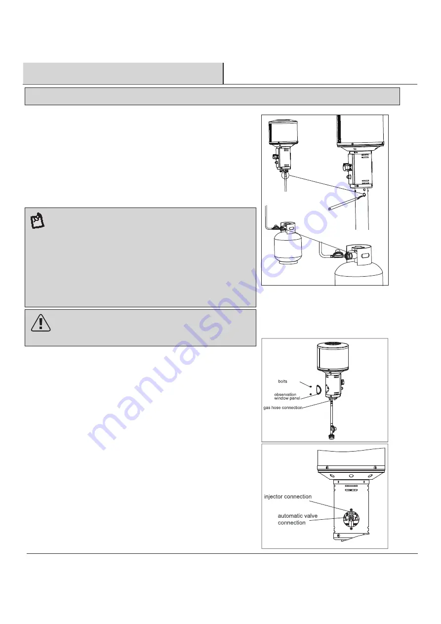
Safety Check
hose
connection
brush
Check for leaks
All connection on the patio heater have been checked for leakage at the factory.
In transportation and handling some connections may have loosened.
Follow these steps to check the gas hose/regulator/cylinder connections:
1) Make leakage solution by mixing 1 part liquid dish soap and 3 parts water.
2) Spoon or brush several drops (or use squirt bottle) of the solution onto hose
connection, regulator & cylinder connection.
3) Turn on gas cylinder valve. Inspect the connections and look for bubbles.
4) If no bubbles appear, the connection is safe.
5) If bubbles appear, there is leakage. Loosen and re-tighten this connection.
If connection still leaks, please call customer service:
Note:
1) The cylinder supply system must be arranged for vapor withdrawal;
2) The cylinder used must include a collar to protect the cylinder valve.
The hose assembly must be replaced prior to the appliance being put into
operation if there is evidence of excessive abrasion or wear, or if the hose
is damaged.
At least once a year, a complete inspection of the entire gas path
components should be performed.
If there is need to replace parts, proceed to leak test after reassembly
(These procedures should be performed by a professional technician).
regulator & cylinder
connection
WARNING : ONLY AN AUTHORIZED GAS TECHNICIAN SHOULD INSTALL THIS PRODUCT.
M5X10
WARNING:
ONLY AN AUTHORIZED GAS TECHNICIAN SHOULD INSTALL
THIS PRODUCT. PROPER ASSEMBLY IS THE RESPONSIBILITY OF THE
INSTALLER.
Annual check operation:
a. Remove the observation window panel by un-screwing two bolts.
b.Turn on LP gas cylinder valve.
c. Spoon severla drops (or use squirt bottle) of the solution onto gas hose
connection and automatic valve connetion and the injector connection.
d. lnspect the connections and look for bubbles.
e. If no bubbles appear, the connection is safe.
f. If bubbles appear, there is a leak. Shut off the LP gas cylinder valve, loosen and
then re-tighten this connection.
g. Check for leaks again.
h. If bubbles still appear, close the LP gas cylinder valve and claa our customer
service line 1-866-814-0585. Do not attempt to use the heater.
i. Hose checking step:
(1) Unscrew M6 X 14 screw from the pole.
(2) Pull out the head assembly, hose & regulator from the pole.
(3) Check if there are cracks or worn sections on the hose. If yes, replace the
hose & regulator immediately.
(4) Check for leaks according to the above step by step after replacing the
hose & regulator.


