


6.
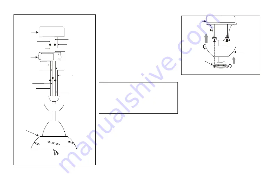
Figure 11
Outlet box
Hanger
bracket
Canopy
Canopy
cover
Screws
Finishing the Installation
Step 1.
Tuck connections neatly into ceiling
outlet box.
Step 2.
Slide the canopy up to ceiling and
over the 2 screws on the hanger bracket.
R o t a t e c a n o p y c l o c k w i s e . N e x t , w h i l e
holding the canopy with one hand, slide the
canopy cover over the screws and rotate
clockwise until tight.
Note:
adjust the canopy
screws as necessary until the canopy and
canopy cover are snug. (Fig. 11)
WARNING
Make sure the notch on the hanging
bracket properly sits in the groove in the
hanger ball before attaching the canopy to
the bracket by turning the housing until it
drops into place.
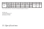
Figure 10
White (neutral)
White (neutral)
Green or bare
copper (ground)
White ("AC IN N")
White ("to motor N")
Ground
(green)
(Connect to
ground wire on
hanger bracket
if no house
ground wire
exists.)
Outlet box
Black (hot)
Black ("AC IN L")
Black ("to motor L")
Receiver
Blue ("for light")
Blue (light)
Black (motor)
SUPPLY CIRCUIT
Fan


