background image

Problem

Fan will not start.

Fan sounds noisy.

Remote control 
malfunction:

Solution

1.Check circuit fuses or breakers.

2. Check line wire connections to the fan and switch wire connections in the switch housing.
    

CAUTION

: Make sure main power is off.

3. Check to make sure the dip switches from the transmitter and receiver are set to the same frequency.

1. Make sure all motor housing screws are snug.

2. Make sure the screws that attach the fan blade bracket to the motor hub is tight.

3. Make sure wire nut connections are not rubbing against each other or the interior wall of the switch housing.
    

CAUTION

: Make sure main power is off.

4. Allow a 24-hour "breaking-in" period.  Most noise associated with a new fan disappear during this time.

5. If using an optional light kit, make sure the screws securing the glassware are tight.  Check that 

light bulb 

is also secure.

6. 

7. Make sure the upper canopy is a short distance from the ceiling. 

 It should not touch the ceiling.

the 

Do not connect the fan with a wall  mounted variable speed control (s)

1. Do not connect the fan with a wall  mounted variable speed control (s)

2. Make sure the dip switches are set correctly.

Troubleshooting 12.  

Summary of Contents for Thorton

Page 1: ......

Page 2: ......

Page 3: ...eeling Brass finishes of this type give their longest useful life when protected from varying weather conditions A certain amount of wobble is normal and should not be considered a defect Servicing pe...

Page 4: ...Safety Rules Unpacking Your Fan Installing Your Fan Installing the Light Kit Your Care of Your Fan Troubleshooting Specifications Operating Transmitter 1 2 3 8 10 11 12 13 Table of Contents...

Page 5: ...al connections spliced conductors should be turned upward and pushed carefully up into the outlet box The wires should be spread apart with the grounded conductor and the equipment grounding conductor...

Page 6: ...ng a Mounting hardware 3 plastic wire connectors b Blade support plates 5 c Blade attached hardware 16 screws with lock washers a c b 13 Unpacking Your Fan 2 1 2 3 5 4 6 7 9 8 10 11 12 7 Light holder...

Page 7: ...building structure Use appropriate fasteners and building materials The outlet box and its support must be able to fully support the moving weight of the fan at least 50 lbs Do not use plastic outlet...

Page 8: ...Fig 7 a half turn WARNING FAILURE TO PROPERLY INSTALL LOCKING PIN AS NOTED INSTEP 7 COULD RESULT IN FAN LOOSENING ANDPOSSIBLYFALLING Step 8 Tighten two set screws on top of the fan motor firmly Figur...

Page 9: ...rom the fan to the Blue wire marked For Light from the receiver Secure wire connections with the plastic wire nutsprovided Step 3 Figure 10 Receiver to House Supply Wires Electrical Connections Connec...

Page 10: ...te adjust the canopy screws as necessary until the canopy and canopy cover aresnug Fig 11 WARNING Make sure thenotch on thehanging bracket properly sitsin the groovein the hanger ball beforeattaching...

Page 11: ...orrect most fan wobble Check after each step 1 Check that all blade and blade bracket screws are secure 2 Most fan wobble problems are caused when blade levels are unequal Check this level by selectin...

Page 12: ...r your fan m NOTE Before starting installation disconnect the power by turning off the circuit breaker or removing the fuse at fuse box Turning power off using the fan switch is not sufficient to prev...

Page 13: ...the wire connector from the fan to the lamp then install the lamp 22W to the light plate using the 3 lamp holders to prop up the lamp Be sure to pull the lamp holders out a little for installing the...

Page 14: ...n a higher setting without affecting your comfort Cool weather Reverse An upward airflow moves warm air off the ceiling area as shown in Figure 20 This allows you to set your heating unit on a lower s...

Page 15: ...not use water when cleaning This could damage the motor or the wood or possibly cause an electrical shock 3 You can apply a light coat of furniture polish to the wood blades for additional protection...

Page 16: ...3 Make surewire nut connectionsare not rubbingagainst each otheror the interiorwall of theswitch housing CAUTION Make suremain power isoff 4 Allowa 24 hour breaking in period Most noiseassociated with...

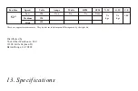
Page 17: ...s andWattage used by the light kit RPM CFM N W G W C F 52 120 3 04 Xx kgs Xx kgs Xxx Xx Xx Xxxx 120 120 Fan Size Speed Volts Amps Watts Low Medium High 13 Specifications Distributed by Your Other Ware...

Reviews: