
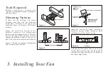
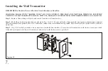
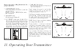
Provide strong support
Recessed
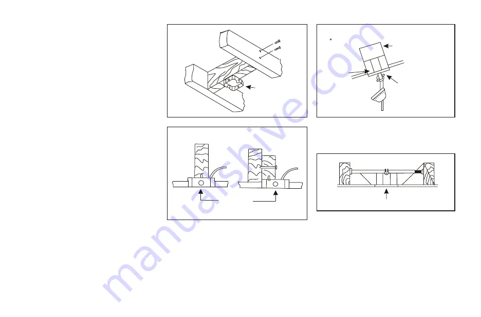
outlet box
Mounting bracket
opening must be
toward the top
Angled ceiling
maximum
24 angle
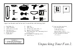
3. Installing Your Fan
Tools Required
P h i l l i p s s c r e w d r i v e r , s t r a i g h t s l o t
screwdriver, adjustable wrench, step ladder,
and wire cutters.
Mounting Options
If there isn't an existing CUL listed
mounting box, then read the following
instructions. Disconnect the power by
removing fuses or turning off circuit
breakers.
Secure the outlet box directly to the
b u i l d i n g s t r u c t u r e . U s e a p p r o p r i a t e
fasteners and building materials. The outlet
box and its support must be able to fully
support the moving weight of the fan (at
least 50 lbs). Do not use plastic outlet boxes.
Figures 1,2 and 3 are examples of different
ways to mount the outlet box.
Note:
You may need a longer downrod to
m a i n t a i n p r o p e r b l a d e c l e a r a n c e w h e n
installing on a steep, sloped ceiling.
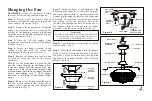
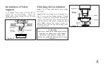
To hang your fan where there is an existing
fixture but no ceiling joist, you may need an
installation hanger bar.(Fig.4) (available at
any Home Depot store).
Outlet box
Outlet box
Outlet box
Figure 1
Figure 3
Figure 2
Figure 4


