background image

6.

WARNING

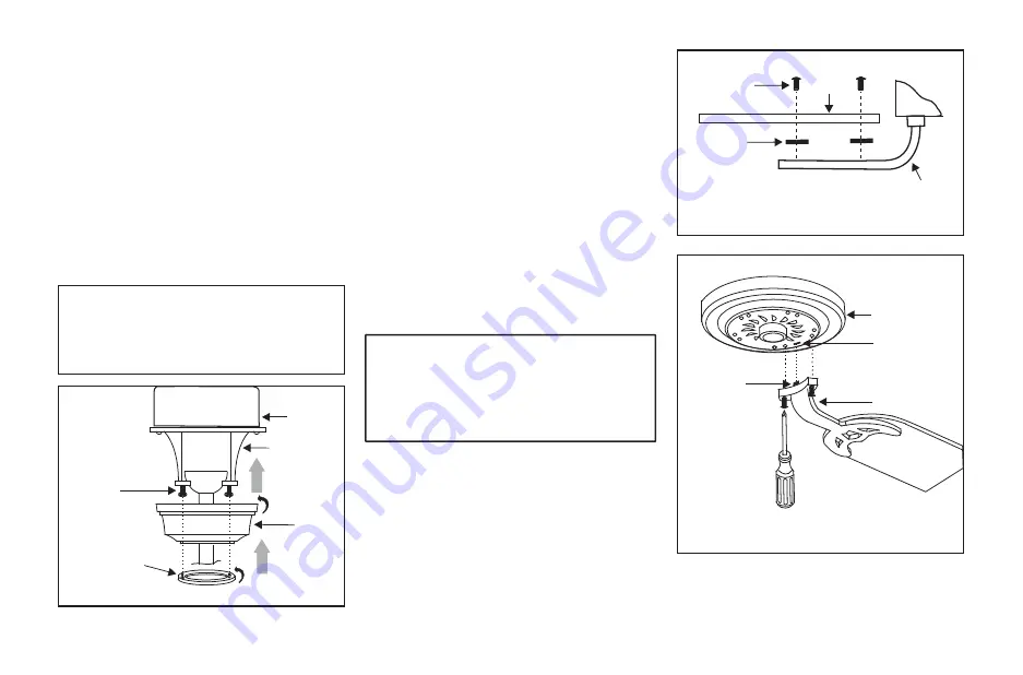
Make sure the notch on the hanging bracket 

properly sits in the groove in the hanger ball 

before attaching the canopy to the bracket by 

turning the housing until it drops into place.

Outlet box

Canopy
cover

Canopy

Hanger
bracket

Figure 10

Screws

Finishing the Installation

Step 1. Tuck connections neatly into ceiling 
outlet box.

Step 2. Slide the canopy up to ceiling and over 
the 2 screws on the hanger bracket. Rotate 
canopy clockwise. Next, while holding the 
canopy with one hand, slide the canopy cover 
over the screws and rotate clockwise until tight. 

Note:

 adjust the canopy screws as necessary 

until the canopy and canopy cover are snug. 
(Fig. 10)

Figure 11

Figure 12

Motor

Blade arm

Slot

Tab

Rubber
washer

Blade
arm

Screws

Blade

Attaching the Fan Blades

Step 1 Attach blades to blade arms using three 
screws and rubber washers as shown in Figure 
11. Start a screw into the arm, do not tighten.  
Repeat for the 2 remaining screws and washers.

Step 2 Tighten each screw securely starting with 
the center screw. Make sure the blade is straight. 
Repeat steps for the remaining blades.

Step 3 Fasten the blade arms to the motor by 
inserting the tab from the blade arms to the slot 
in the bottom motor housing, then tighten the 
two screws and washers already installed in the 
blade arms (Fig. 12).

WARNING

TO REDUCE THE RISK OF PERSONAL INJURY, 

DO NOT BEND THE BLADE ARMS WHILE 

INSTALLING, BALANCING THE BLADES, OR 

CLEANING THE FAN.  DO NO  INSERT FOREIGN 

OBJECTS BETWEEN ROTATING FAN BLADES.

Summary of Contents for WITHROP 656 413

Page 1: ......

Page 2: ...type give their longest useful life when protected from varying weather conditions A certain amount of wobble is normal and should not be considered a defect Servicing performed by unauthorized person...

Page 3: ...Table of Contents Safety Rules Unpacking Your Fan Installing Your Fan Installing the Light Kit Operating Your Fan Care of Your Fan Troubleshooting Specifications 1 2 3 8 9 10 11 12...

Page 4: ...7 feet clearance from the trailing edge of the blades to the floor 7 Do not operate the reverse switch while the fan blades are in motion The fan must be turned off and the blades stopped before reve...

Page 5: ...nopy assembly 3 Ball downrod assembly 4 Coupling cover 5 Fan motor assembly 6 Blade arms 5 12 Loose parts bag containing a Electrical hardware Screws 2 PCs Lock washers 2 PCs Metal washers 2 PCs 3 pla...

Page 6: ...moving weight of the fan at least 50 lbs Do not use plastic outlet boxes Figures 1 2 and 3 are examples of different ways to mount the outlet box 3 Installing Your Fan Outlet box Outlet box Figure 1...

Page 7: ...iting from the top of the fan motor through the coupling cover canopy cover canopy and then through the ball downrod Fig 7 Step 7 Align the holes at the bottom of the downrod with the holes in the col...

Page 8: ...n fan ground wires located on the mounting plate and motor to the household ground wire Step 4 After connecting the wires spread them apart so that the green and white wires are on one side of the out...

Page 9: ...are snug Fig 10 Figure 11 Figure 12 Motor Blade arm Slot Tab Rubber washer Blade arm Screws Blade Attaching the Fan Blades Step 1 Attach blades to blade arms using three screws and rubber washers as s...

Page 10: ...screws from the mounting ring and keep it for future use Loosen the other 2 screws Do not remove 2 Place the key holes on the switch housing over the 2 screws previously loosened from the mounting ri...

Page 11: ...white Black to black 4 Carefully push all wires back into the switch housing Place the key holes on the light kit over the 2 screws previously loosened from the switch housing turn light kit until it...

Page 12: ...Speed settings for warm or cool weather depend on factors such as the room size ceiling height number of fans and so on The slide switch controls directions forward switch down or reverse switch up W...

Page 13: ...ching the finish The plating is sealed with a lacquer to minimize discoloration or tarnishing Do not use water when cleaning This could damage the motor or the wood or possibly cause an electrical sho...

Page 14: ...s type of control choose and install another type of control 7 Make sure the upper canopy is a short distance from the ceiling It should not touch the ceiling 1 Check that all blade and blade arm scre...

Page 15: ...RPM CFM N W G W C F 52 1 32 m Low Medium High 120 120 120 These are approximate measures They do not include Amps and Wattage used by the light kit Distributed by Home Depot of Canada Inc 900 1 Conco...

Reviews: