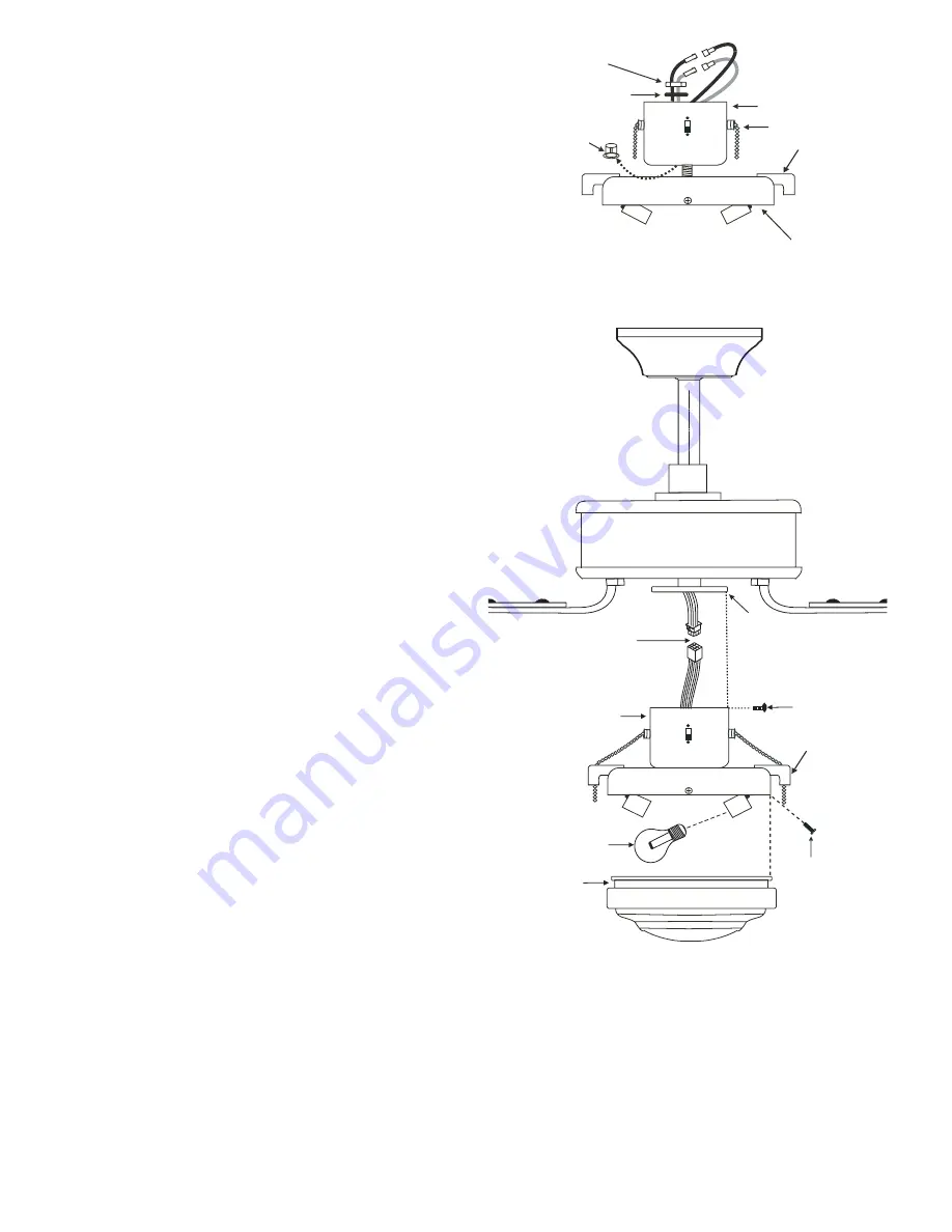
background image

7

Figure 14

Figure 15

9.  INSTALLING THE LIGHT  

KIT 

NOTE: Before starting installation, 

disconnect the power by turning off the 

circuit breaker or removing the fuse at 

fuse box.

Turning power off using the fan switch is 

not sufficient to prevent electric shock.

1. Remove the plug from the switch 

housing (Fig. 17), attach the light kit to the 

switch housing by feeding the light kit 

wires (black and white) through the hole 

of switch housing and then screw it onto 

the switch housing by nut & lock washer 

provided. Be sure it is tight enough to 

prevent light kit from vibrating loose. 

NOTE: For easy pull chain installation, be 

sure that the location of the 3 speed 

switch on the switch housing and the pull 

chain holder on the light kit are in suitable 

locations as shown on Fig. 14 and 15. 

2. Locate two single white and blue wires 

in the switch housing labeled  FOR LIGHT. 

3.  Make the polarized plug connections:

       - White to white  

       - Blue to black

4. While holding the light kit assembly 

under your fan, snap together the wire 

connection plugs .

5. Carefully push all wires back into the 

switch housing, then install the light kit 

assembly onto the mounting plate with 3 

screws provided. Be sure to tighten all 

screws. (Fig. 15) 

6. Pass the two pull chains on the switch 

housing through the chain holders 

located on the light kit, install the fobs to 

the pull chains. (Fig. 15)

7. Install two 60 watt (max.) bulbs 

(included) and glass shade with four 

thumb screws, do not over tighten.

8. Restore power and your light kit is ready 

for operation.

9. If the light kit does not work, turn off the 

electricity and lower either canopy on 

your ceiling fan to make sure the blue wire 

is connected to the black household wire.

Switch housing 

Light kit

Nut

Lock washer

Pull chain 

Plug

Pull chain holder

Mounting plate

Connection plug

Screws

Thumb screws

Light kit assembly

Glass shade

Bulbs

Pull chain holder

Summary of Contents for Y52YH5-06

Page 1: ...READ AND SAVE THESE INSTRUCTIONS FAN RATING AC 120V 60Hz UL LISTED MODEL AC 552 MODEL Y52YH5 06 CEILING FAN INSTALLATION AND OPERATION INSTRUCTION...

Page 2: ...Fan motor assembly f Set of blade brackets 5 g Switch housing h Light kit i Glass shade j Pull chain and fob 2 k 60 Watt medium base bulbs 2 l Package hardware 1 Mounting hardware wire nuts 3 2 Blade...

Page 3: ...lades are in motion Fan must be turned off and blades stopped before reversing blade direction 8 Avoid placing objects in the path of the blades 9 To avoid personal injury or damage to the fan and oth...

Page 4: ...let box and its support must be able to fully support the moving weight of the fan at least 50 lbs Do not use plastic outlet boxes Figures 1 2 and 3 are examples of different ways to mount the outlet...

Page 5: ...aps into its locked position Fig 6 Step 6 Tighten two set screws on top of the fan motor firmly Fig 6 Step 7 Place the downrod ball into the hanger bracket socket Fig 7 CHANGING THE DOWNROD OPTIONAL N...

Page 6: ...ecting nuts upward and push the wiring into the outlet box Figures 9 and 10 illustrate the wiring connections for optional wall control The wire color out of wall control may vary see wall control s i...

Page 7: ...igure 12 Start a screw into the bracket but do not tighten Repeat for the other 2 screws and washers Step 2 Tighten each screw securely starting with the center screw Make sure the blade is straight S...

Page 8: ...witch housing labeled FOR LIGHT 3 Make the polarized plug connections White to white Blue to black 4 While holding the light kit assembly under your fan snap together the wire connection plugs 5 Caref...

Page 9: ...oom size ceiling height number of fans and so on The slide switch controls directions forward switch down or reverse switch up W a r m w e a t h e r F o r w a r d A downward airflow creates a cooling...

Page 10: ...each other or the interior wall of the switch housing CAUTION Make sure main power is off 4 Allow a 24 hour breaking in period Most noise associated with a new fan disappear during this time 5 If usin...

Page 11: ...s They do not include Amps and Wattage used by the light kit 12 SPECIFICATIONS Fan Size Speed Volts Amps Watts RPM CFM N W G W C F 52 120 120 120 0 20 0 35 0 49 7 25 56 57 111 163 1025 3500 5400 9 7 k...

Reviews: