EZMaster
EZMaster
User’s Guide
Page 31 of 53
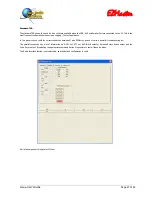
Band Map Pulse frame
The normal outputs on the Matrix connector are Line-ON or Line-OFF steady levels to drive external devices, such as antenna relay or
filter boxes, or any other devices that are needed for a particular purpose. Some devices, such as Step by Step relays, need only a
pulse command to excite the coil and for this purpose, by enabling the Pulse A / Pulse B check box, EZMaster will output only a pulse at
the corresponding Matrix A/B output connector. The sliders, under both the check buttons, define the length of the pulse, and the
minimum elapsed time between pulses. This capability allows the use of several hardware configurations, even homemade and/or with
slow old, step-by-step, 50A relays.
Band Map Delay frame
The two sliders define a delay time between the Matrix A/B output and the drop of the associated PTT line.
The default value is 0. These commands are useful to assure that the antenna relays are really closed before applying RF, which can be
very dangerous particularly when the TX antenna setup is different from the RX one: for instance, receiving with a beverage antenna
and transmitting with an array in different directions. In such environments the RX-TX switch needs to (must) be executed without any
RF applied to avoid amplifier, antenna, cables or connectors failures and damages. Most of the commercial devices need no more that
20 – 50 ms to switch from OFF to ON status.
PTT Delay frame
The two sliders define a time between the closure of the PTT and the PTT DELAYED output. For safety reasons it is always better to
close the Amplifier Relay before dropping the Radio PTT line. The devices connected to the PTT connector are closed immediately on
receiving the command and the devices connected to the PTT DELAYED line are activated after the user-defined delay time.
The default value is 0, and suggested values are in the range from 50 to 100 ms, depending on the connected devices. The PTT lines
connected to the radios via the MIC or via the RTTY connectors are a DELAYED PTT line.
This delay time is added to the BAND MAP DELAY time mentioned before.
Speaker frame
Radio A/B
By selecting this checkbox, the headphone output is routed from RADIO B, while usually it is connected to RADIO A. This
function selects only the headphone output and does not change the other SO2R functions behavior for the microphone or
the CW keyer.
Split
The checking of this box enables the stereo with two radios and a stereo headphone. Radio A audio is routed on the right ear
and Radio B audio on the left ear.
Reverse
The checking of this box “reverse” the RADIO audio into the headphone. Radio A audio is routed on the left ear and Radio B
audio on the right ear.
Automatic
The checking of this box enables the Automatic Speaker switch. This function switches the headphones to the unused RADIO
while the other one is in TX.
A very common configuration is to listen from RADIO B, when Calling CQ on RADIO A, to optimize the multiplier’s hunting by
tuning for new stations and monitoring the right time to call them on one radio while Cqing with the other.
These functions can be enabled at the same time, thus allowing a configuration that enables listening on both radios, when split has
been enabled, and then switches to “RADIO B only” when transmitting, performing the best solution for an high-end demanding user.
Speaker Delay frame
This function works in conjunction with the Automatic Speaker command. The slider defines a waiting time, in milliseconds, before
switching the speakers on the unused radio. This is very useful when you want to monitor your transmission, for a while, before
switching the headphones to the second radio.

