©1999 Hamtronics, Inc.; Hilton NY; USA. All rights reserved. Hamtronics is a registered trademark. Revised: 1/28/00
- Page 3 -
about five inches, starting at the
lower right-hand corner of the
board.
n. Using suitable static protec-
tion described earlier, carefully un-
pack the ISD-1020A ic and install it
in the socket. Be sure to orient it
with notch as shown. Be careful
that all the pins actually go into the
socket. It is easy for some to bend
underneath or extend over the out-
side of the socket. Do not bend any
of the pins excessively, as they may
break from repeated stress.
o. This completes assembly.
Check over construction to be sure
all parts are installed in proper
places, with proper polarities, and
check solder connections for any
cold solder joints, solder splashes,
etc. Check that the indicated holes
are empty and that components
were not accidentally installed in
the wrong holes. If any parts are
missing, check to be sure that other
parts are not left over; since a part
may have been installed in the
wrong place. There should be four
screws left over.
INSTALLATION.
Mounting.
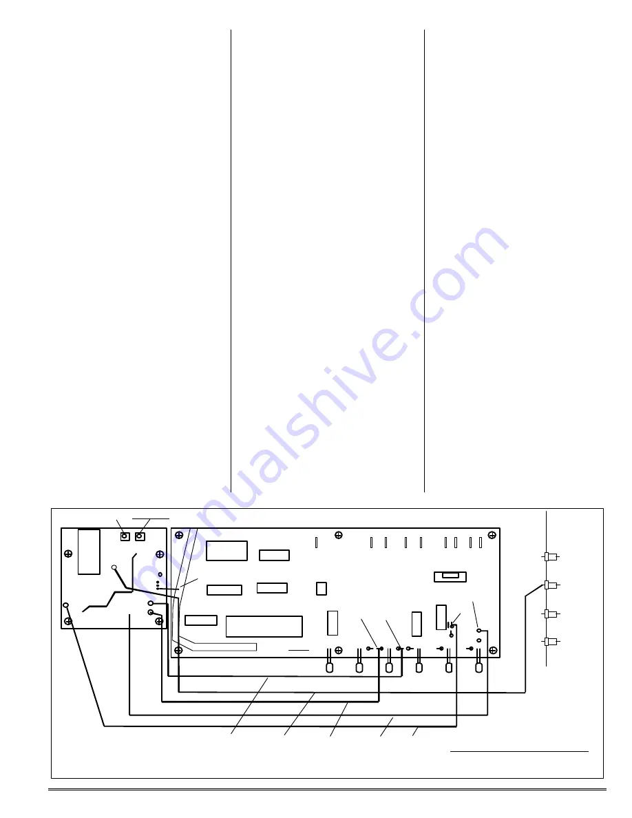
Four mounting holes should have
been drilled in the repeater chassis
before assembling the DVR-3 pc
board. Now, set the board in place
as shown below, and secure with
four 4-40 x ¼ inch screws.
Caution: The digital recorder ic is
static sensitive. Use suitable handling
precautions, including grounding your-
self, to avoid damage.
Wiring.
Dress the wire leads away from
the DVR-3 board, as shown in the
diagram below, along the front edge
of the COR-5 board, and under the
LED leads. Dress individual lead
ends and solder as follows.
a. Connect the gray "audio out-
put" wire to the loop at the top of R8
on the COR-5 board. Check that the
resistor is oriented as shown, be-
cause the loop at the top of the re-
sistor would be connected to the
wrong point if the resistor was inad-
vertently reversed when the COR-5
board was assembled. Wrap the
wire around the resistor lead, and
tack solder.
b. Connect the brown "playback
control" wire to the Voice ID Trip
output pad at the right-front corner
of the COR-5 board. (This is the pad
which used to be called "Aux. #2"
before the DVR-3 was available.)
Insert the stripped end of the lead
into the hole just enough to hold it,
and solder from the top of the board.
c. Connect the blue "key car-
rier" wire to the top lead of R34, as
shown in the diagram. Check that
the resistor is oriented as shown,
because the loop at the top of the
resistor would be connected to the
wrong point if the resistor was inad-
vertently reversed when the COR-5
board was assembled. Wrap the
wire around the resistor lead, and
tack solder.
d. Connect the yellow "record
control" wire to the top lead of R38,
as shown in the diagram. Check
that the resistor is oriented as
shown, because the loop at the top
of the resistor would be connected
to the wrong point if the resistor
was inadvertently reversed when
the COR-5 board was assembled.
Wrap the wire around the resistor
lead, and tack solder.
e. Connect the green "rcvr
audio" wire to the third feedthrough
capacitor from the front along the
receiver compartment shield. This
feedthrough has an existing gray
wire connected to the audio input of
the COR-5 board. Leave the original
wire and add the new green wire.
f.
The DVR-3 board gets its
+5Vdc power directly from the 5V
trace on the top of the COR-5 board.
Bring the bus wire lead previous in-
stalled on the DVR-3 board from the
+5V input pad on that board across
to lay on top of the +5V bus trace on
the COR-5 board as shown, and trim
the length. Tack solder to the foil.
Check to be sure that there is no
short circuit to any other foil traces.
B+
AUDIO OUT
KEY
R8
VOICE ID TRIP PAD
DVR-2
COR-5
BROWN
GRAY
BLUE
R34
TACK SOLDER TO +5V BUS
S1 - Playback
S2 - Record
AF FT CAP
R6
AF IN
R38
YELLOW
GREEN
TRIP
View of Installation in Repeater


