©1995 Hamtronics, Inc.; Hilton NY; USA. All rights reserved. Hamtronics is a registered trademark. Revised: 12/14/02
- Page 3 -
7/64" and the coil is down close to the
board as instructed earlier.
TROUBLESHOOTING.
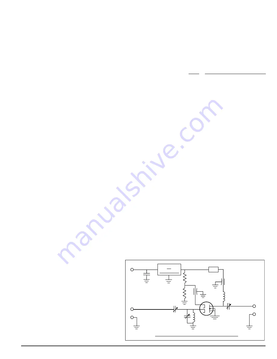
Since the unit is fairly simple,
troubleshooting usually is limited to
checking the dc voltages on the tran-
sistor. These will vary somewhat;
however, in general, the gate-2 voltage
should be about 4 Vdc, and the drain
should be at about 8 Vdc. The source
and gate 1 should be at ground poten-
tial.
If the dc voltages are OK but the
unit is no longer amplifying, assuming
there are no problems in the coax ca-
bling, the transistor may have been
damaged by transmitter rf or static
discharge at the antenna. Such dam-
age often does not cause a change in
the dc characteristics of the transis-
tor.
If the drain voltage is much lower
than 8 Vdc, first disconnect ferrite
bead Z1 to see if the transistor is
shorting the output of the voltage
regulator. In the case of a severe volt-
age transient or reverse B+ voltage, it
is possible to also damage the voltage
regulator.
If the unit is amplifying OK but
you are experiencing intermod, you
may be overloading your receiver by
adding gain ahead of the rf stage.
Low noise preamps are effective in
improving sensitivity of receiver sys-
tems in weak signal areas. However,
it is normally considered inadvisable
to use a preamp, even with a well de-
signed receiver, in very strong signal
areas, such as the center of a city or
other locations with high powered
transmitters in the area.
Adding gain ahead of a receiver
degrades the selectivity of a receiver
by an equivalent amount by boosting
undesirable signals as well as desir-
able ones. In severe cases, strong
signals which do not cause intermod
by themselves will create intermod in
the rf stage or mixer of your receiver
after being amplified an additional 20
dB.
If you use a preamp with a re-
peater receiver, you will need to have
additional rejection in your duplexer
to attenuate your transmit signal that
much more to prevent desense.
TRANSISTOR
REPLACEMENT.
Transistor replacement is compli-
cated a little by the fact that the pc
board has plated-through holes. You
must remove all the solder from the
drain and gate-1 leads before trying to
pull the transistor off the board. This
can be done with solder-wick or a
vacuum desoldering tool, as long as
you remove all the solder within the
holes. Then, melt the solder on the
top of ft cap C5, and lift the gate-2
lead of the transistor. Finally, melt
the solder on the source lead, and re-
move the transistor from the board.
/
CAUTION: The small geometry
and high impedances make fet's heat
and static sensitive; so be careful.
Wear a wrist strap or discharge your
hand to a grounded metal object just
before picking up the transistor. The
use of a grounded soldering iron is
mandatory. A heat sink is not neces-
sary while soldering, but be careful not
to apply any more heat than necessary.
You should not be overly anxious
about blowing out the transistor if you
observe the precautions above. The
transistors are all factory tested and
protective wrapped to ensure that they
arrive in good condition. There is no
warranty coverage for damage which
occurs in handling.
Refer to ASSEMBLY section of
manual for details of how to install a
transistor.
REMOVING OTHER PARTS.
Because the pc board uses plated
through holes, all of the solder within
the holes must be removed before a
lead can be removed from the board.
This can be done with solder-wick or a
vacuum desoldering tool, as long as
you remove all the solder within the
holes.
PARTS LIST.
Ref # Description
C1-C3 4.5 pf cer. variable
C4 not
used
C5
.001µf feedthrough capacitor
C6 not
used
C7
0.15µf mylar capacitor
C8
.001µf feedthrough capacitor
L1-L2 #20 bus wire wound as per
Assembly information
Q1
N.E.C. 3SK122 mosfet
R1-R2 100K
U1
78L08 Voltage Regulator IC
Z1 Ferrite
Bead
Z1
L1
Figure 4. LNW-450 Preamp, Schematic Diagram
8-VOLT REG.
U1
E5
B+
(10-15V)
C7
R1
R2
E3
E4
INPUT
RF
C5
C1
C2
Q1
L2
C8
C3
E2
E1
OUTPUT
RF


