©1995 Hamtronics, Inc.; Hilton NY; USA. All rights reserved. Hamtronics is a registered trademark. Revised: 1/31/00
- Page 1 -
CONSTRUCTION.
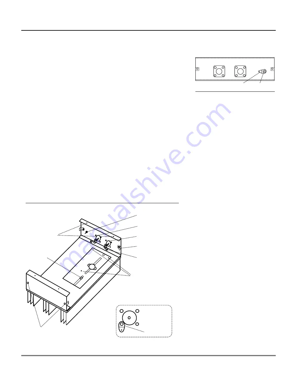
a. Set heatsink on bench, ori-
ented as in figure 1. Note where PA
transistor is to be mounted to two
adjacent holes. Align the pc board
with the heatsink, matching the cut-
out for the transistor and the pc
board mounting holes with the holes
on the heatsink.
Note that the heatsink
is used for several products; so there
will be extra holes to the left of the pc
board which are not used in this model.
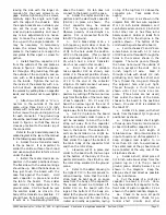
b. Temporarily remove the pc
board, and lay it on a box or hold it in
a vise horizontally with the etched
side of the board up. Using a sharp
pick or any other convenient tool,
pick up eyelets and place them in the
small holes on the board. The heads
of the eyelets must rest flat against
the foil on the etched side of the
board. Then, using a small amount
of solder, solder the heads of the
eyelets to the foil. The eyelets con-
nect the pc board front and rear
ground planes together at critical lo-
cations. Be sure all small holes are
thus connected through. If you lose
an eyelet, bus wire can be used.
c. Turn the pc board over, and
solder the other side of the eyelets to
the ground plane. Be sure all are
soldered, and check to make sure
none have slipped back through the
other side. If so, heat eyelet flange
on top side of board until solder on
both sides melts, and push eyelet
gently back in place. Note that it is
especially important that the 8 eye-
lets under the emitter leads of Q1
are properly seated and that no sol-
der blobs protrude above eyelet
heads. This is to prevent stress on
transistor leads when it is later in-
stalled.
d. Set two #8 flat washers over
each of the 3 enclosure holes used to
mount the pc board (not the 2 tran-
sistor holes).
The two washers provide
the proper thickness for the pc board
spacing needed for the transistor; so be
sure to use the ones supplied to prevent
damage to the transistor.
Set the pc
board in place, and secure with three
each 6-32 x 3/8 inch thread cutting
screws. The screws go through the
pc board and spacer washers and
thread into the aluminum heatsink.
Be careful not to over tighten the screws
and strip the threads.
SOLDER LUG
FEEDTHRU CAP.
Figure 2. Outside View of End Plate.
J2 - OUTPUT
J1 - INPUT
C14 - PWR
e.
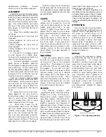
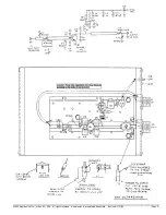
Locate the power transistor,
and note that the collector lead is
the narrow one (see component loca-
tion diagram). The collector lead
should face the right-hand side (to-
ward connectors). Apply a small
amount of heatsink compound to the
bottom surface of the transistor, and
set it in place through the cutout in
the board.
f. Secure the transistor with two
4-40 x 5/8 inch screws inserted
through the transistor flange into the
heatsink. Use lockwashers and nuts
on the fin side of the heatsink. Align
the transistor with the board before
tightening screws.
g. There are two end plates: one
has holes for connectors. Each end
plate has two clearance holes for at-
tachment to the heatsink and two
Pem nuts which allow the cover to be
secured. Position the end plate with
holes for connectors as shown, and
attach to heatsink with two 4-40 x
3/8 inch screws through the heat-
sink and two 4-40 nuts on the flange
of the end plate. In like manner, at-
tach the end plate without connector
holes on the other end of the heat-
sink. Before tightening screws, align
the end plates carefully with the
edges of the heatsink so the cover
later fits neatly.
h. The cover is secured to the
chassis with four angle brackets,
which are threaded on both sides but
have slightly different dimensions on
the two sides. It is important to in-
stall them correctly. These angle
brackets should be fastened to the
inside of the chassis as shown in the
diagram, using 4-40 screws. The leg
with the
shorter
dimension from the
bend to the hole goes over the screw,
HAMTRONICS® RPA-30 UHF REPEATER POWER AMPLIFIER
HAMTRONICS® RPA-30 UHF REPEATER POWER AMPLIFIER
ASSEMBLY, OPERATION, & MAINTENANCE INSTRUCTIONS
ASSEMBLY, OPERATION, & MAINTENANCE INSTRUCTIONS
Feedthru Capacitor C14
Input Connector J1
Output Connector J2
Angle Bracket (typical)
4-40 Nut with 4-40
Screw From Below
Be Careful Not To Remove These
Screws When Removing Cover.
Pem Nuts To
Attach Covers
Figure 1. Bottom View of Heatsink and End Plates
Note Position
of Solder Lug
on Connectors
Mounting Screws
Hole Not Used


