©1995 Hamtronics, Inc.; Hilton NY; USA. All rights reserved. Hamtronics is a registered trademark. Revised: 1/31/00
- Page 2 -
leaving the side with the longer di-
mension for the cover screws to en-
gage. Before tightening the screws,
carefully align the angle nuts flush
with the edge of the chassis. After
the angle brackets are installed, you
can set the cover over the heat-
sink/end plate assembly and see if
any minor adjustments are neces-
sary to make the cover screw holes
line up with the angle brackets. It
may be necessary to temporarily
loosen the screws holding the end
plates to the heatsink to realign the
end plates farther apart or closer to-
gether.
i. Install feedthru capacitor C14
from the outside of the end plate as
shown in figure 2. Insert the capaci-
tor through a #8 ground lug, through
the outside of the end plate, and se-
cure with a #8 lockwasher and nut
on the inside. Tighten the nut on
the inside of the assembly with a ¼-
inch nut driver.
Be careful not to break
the ceramic by putting force on capacitor
leads, and be careful not to over tighten
nut.
j. Attach two SO-239 or 'N' con-
nectors to the outside of the end
plate, using three 4-40 x 1/4 inch
screws with nuts and one 4-40 x 3/8
inch screw with a ground lug and nut
for each connector. The ground lugs
should be positioned as shown in the
inset in figure 1 so that they are as
close as practical to the center lug of
the connectors.
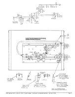
Refer to the pc board component lo-
cation diagram in the rear of the manual
for the following assembly operations.
k. Solder the six transistor leads
to the pc board. It is important to
solder the entire surface of each lead
and use enough solder to form a bond
under the leads.
l. Install the metal clad mica ca-
pacitors in the exact positions shown.
The flat side with the value markings
should be up. Bend the tabs down so
they just touch the board with the
case flat against the board. Hold
each capacitor in place and solder
the tab to the board. Then, solder
each side of the metal case to the
ground plane. C3-C6 should be over
the emitter leads, as close to the
body of the transistor as possible. C7
should have its tab bent up slightly.
It acts as a free-standing terminal
above the board. Its tab does not
connect to the board, just the case.
m. Solder the mylar and disc ca-
pacitors and the electrolytic capacitor
(C9-C11) in place as shown. The
.01uF capacitor may be marked
"103". The mylar capacitor is red.
Observe polarity of electrolytic ca-
pacitor. C11 is connected from the
tab of C7 to ground.
n. Cut a brass strap 3/16 x 1
inch (approx.), and solder it down to
complete the stripline from the base
of Q1 to the hole under the position
of C2 on the diagram. (This pc board
was originally designed for another
PA which had a driver transistor
which is not used in this model.)
o. Bend the tabs of variable
mica capacitor C12 as shown, and
solder it in the exact position shown,
on a diagonal from the center contact
of J2 to the end of the collector
stripline. Its leads are bent out away
from the capacitor to reach.
p. Prepare the three piston ca-
pacitors by cutting off the two narrow
lugs from the bottom of the main body
of each capacitor. On C1 and C2,
bend the narrow lugs at the end of
the rotor straps over at a 90-degree
angle away from the capacitor.
q. Set C2 in place on the board
as shown and tack solder in place. It
will be necessary to bend the rotor
strap out away from the capacitor
body at an angle to straddle the large
hole in the board. The capacitor it-
self can be installed on a slight an-
gle, and the strap will be at an angle.
Tack solder the lugs at the bottom of
the main body of the capacitor first
and then the rotor strap.
r. Likewise, set C1 in place and
solder to the board with the two lugs
at the bottom of the body of the ca-
pacitor soldered to the stripline, and
the rotor strap soldered to the ground
plane.
s. Refer to the detail drawing to
the right of C13 in the component lo-
cation drawing. Note that the rotor
strap must be bent up at an angle
away from the body of the capacitor.
The excess should be trimmed off.
Install C13 on the board with the
lugs at the bottom of the body sol-
dered to the ground plane next to the
mounting screw, and the rotor strap,
routed as directly as possible, laying
on top of the lug from C12 above the
connector pin. Tack solder thor-
oughly.
t. Wind coil L1 as shown in the
diagram from #18 bus wire supplied.
It is 1/4 inch inside diameter; so it
can be formed around a 1/4 inch drill
bit or other rod. L1 has three turns
barely spaced. Solder L1 leads from
the tab of C7 to the stripline in the
position shown. The bottom of the
coil should be just above the board.
u. Ferrite chokes Z1 and Z2 are
6-hole balun cores with 1-1/2 turns
of #22 bus wire threaded through the
holes in the manner shown in the
diagram. The turns go only through
the holes, not around the outside of
the core, except at the ends. Cut a
3-inch length of wire. Feed it
through a hole with about 1/2 inch
protruding, and hold this short end.
Then, thread the long end through
the adjacent hole and pull tight.
Thread through a third hole as
shown until 1/1-2 turns are com-
plete. (Three holes are not used.)
Tack solder the leads of the balun
chokes to the board in the positions
shown. One end of Z2 is soldered to
the tab of C7.
v. Solder Z1 in place, with short
leads, from the base of Q1 to ground,
positioned as shown.
w. Strip and solder short length
of hookup wire from B+ land area on
pc board to feedthru capacitor C14.
x. Cut an 8 inch length of
miniature coax. Strip it and solder to
input of board and uhf receptacle J1.
Keep stripped lead lengths to no
more than 1/4 inch to avoid losses.
The center lead at the pc board must
be connected at the very end of the
stripline as shown.
y. Solder a short, direct piece of
3/16 inch wide brass strap from the
ground lug on J2 to the pc board
ground plane directly below J2, as
shown in the diagram. Keep the
strap as short and direct as possible
for low inductance.
z. Cut the leads of a 10pf disc
capacitor to about 1/8 inch. Care-
fully tack solder this capacitor to the
front side of piston capacitor C2 as
shown in the parts location diagram.
aa. Check to be sure all parts
have been installed. Check for po-
tential short circuits and other


