background image

IMPORTANT NOTE

THESE INSTRUCTIONS MUST BE READ 

AND UNDERSTOOD BEFORE INSTALLING, 

COMMISSIONING, OPERATING OR 

SERVICING EQUIPMENT

INSTALLATION, COMMISSIONING AND

SERVICING INSTRUCTIONS

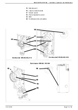
Gas-fired condensing water heater

DORCHESTER DR-SG

Models 

20-210, 25-210, 30-210,
35-356, 50-356, 60-356,

70-538, 80-538, 100-538, 120-538

Summary of Contents for DORCHESTER DR-SG 20-210

Page 1: ...RSTOOD BEFORE INSTALLING COMMISSIONING OPERATING OR SERVICING EQUIPMENT INSTALLATION COMMISSIONING AND SERVICING INSTRUCTIONS Gas fired condensing water heater DORCHESTER DR SG Models 20 210 25 210 30...

Page 2: ...d efficiently Service Contracts Regular routine servicing of equipment by Hamworthy service engineers inspects the safety and integrity of the plant reducing the risk of failure and improving performa...

Page 3: ...5 Electrical connection 22 4 INSTALLATION 23 4 1 Ventilation 23 4 2 Unvented installation 23 4 3 Vented installation 25 4 4 Removing the cover panel 26 4 5 Installing the Dorchester DR SG 26 4 6 Flue...

Page 4: ...DRAULIC DIAGRAMS AND CONFIGURATIONS 51 10 ELECTRICAL VALIDATION 80 11 OPTIMIZATION 80 12 SPARE PARTS LIST 83 13 CUSTOMER REGULATION PARAMETERS TABLE 92 14 APPENDIX A 102 INFORMATION This symbol draws...

Page 5: ...n this case the installer will carefully protect the product to avoid any damage during this handling 1 2 Qualification of personnel for installation adjustment use and mainte nance Boiler installatio...

Page 6: ...the DORCHESTER DR SG we strongly recommend protecting it where it is in contact with the hand truck and the strap ratchet figure 1 Transporting through a doorway Dorchester DR SG XX 538 model INFORMA...

Page 7: ...repair the escape If the source of the gas escape cannot be repaired there and then make the installation safe and apply the procedures contained within IGEM G 11 Gas Industry Unsafe Situations Proced...

Page 8: ...maximum concentration of 30 and an exposure time of less than 24 hours at room temperature 2 APPROVALS 2 1 Compliance with European Directives Low Voltage 2014 35 EU This product is intended for use o...

Page 9: ...3rd family gases Part 1 Specification for installation of gas appliances to chimneys and for maintenance of chimneys Part 2 Specification for the installation and maintenance of ventilation provision...

Page 10: ...lations inside buildings conveying water for human consumption Part 5 Operation and maintenance BS 8558 2015 Guide to the deisgn installation testing and maintenance of services supplying water for do...

Page 11: ...d to loss of the guarantee Gas category Dorchester DR SG XX 210 20 to 30kW II2H3P Dorchester DR SG XX 356 35 to 60kW II2H3P Dorchester DR SG XX 538 70 to 120kW II2H3P 2 3 Gas supply pressures INFORMAT...

Page 12: ...1 1 2 Rp 1 1 2 2 Secondary return Rp 1 1 2 Rp 1 1 2 Rp 1 1 2 3 Cold water inlet Rp 1 1 2 Rp 1 1 2 Rp 1 1 2 4 T P valve UK only Rp 1 Rp 1 1 4 Rp 1 1 2 5 Gas inlet R 3 4 R 3 4 R 1 6 Air inlet 80 100 130...

Page 13: ...on of flue outlet 45 45 45 L Angle position of T P valve fitting 13 15 70 M Angle position of gas connection 12 9 20 20 N Angle position of inspection hatch 45 45 38 O Angle position of HMI 90 90 90 P...

Page 14: ...per powered anode 6 Complete display user interface 7 Fan 8 Air inlet 9 Air valve 10 Air pressure switch 11 Gas valve 12 Gas mixer tap 13 Ignition electrode spark train 14 Triplex sensor behind HMI sc...

Page 15: ...Lower powered anode 17 Smoke nozzle 18 Flue temperature sensor 19 NRV 20 Condensate removal siphon 15 Dorchester DR SG XX 356 Dorchester DR SG XX 538 Dorchester DR SG XX 210 13 01 2023 Page 15 104 DOR...

Page 16: ...of the combustion products circuit C 100 100 100 Nominal operating temperature of the combustion products C 57 58 60 Exhaust outlet interior diameter mm 80 80 80 Maximum allowable nozzle pressure B23P...

Page 17: ...9 16 6 95 0 16 6 Temperature of the combustion products circuit C 100 100 100 Nominal operating temperature of the combustion products C 40 3 50 9 51 6 Exhaust outlet interior diameter mm 100 100 100...

Page 18: ...158 4 32 4 187 2 32 4 Temperature of the combustion products circuit C 100 100 100 100 Nominal operating temperature of the combustion products C 56 8 58 8 59 8 59 3 Exhaust outlet interior diameter...

Page 19: ...Qmin 21 6 7 2 31 7 7 2 38 2 7 2 Temperature of the combustion products circuit C 100 100 100 Nominal operating temperature of the combustion products C 37 53 59 Exhaust outlet interior diameter mm 80...

Page 20: ...h Qn Qmin 42 8 14 4 63 0 14 4 76 7 14 4 Temperature of the combustion products circuit C 100 100 100 Nominal operating temperature of the combustion products C 37 8 48 7 50 8 Exhaust outlet interior...

Page 21: ...n Qmin 93 6 32 4 108 0 32 4 136 8 32 4 187 2 32 4 Temperature of the combustion products circuit C 100 100 100 100 Nominal operating temperature of the combustion products C 53 1 56 3 57 6 58 5 Exhaus...

Page 22: ...the emitted sound power but contrary to the noise level it doesn t correspond to the perceived measurement 3 5 Electrical connection Dorchester DR SG XX 210 Dorchester DR SG XX 356 Dorchester DR SG XX...

Page 23: ...n industrial and commercial premises 4 2 Unvented installation Unvented installations require a number of mandatory safety devices to be installed onto the system to prevent the build up of excessive...

Page 24: ...ut where this is not possible or practically difficult there should be clear visibility at one or other of these locations The following information is taken from Approved Document G3 of the Building...

Page 25: ...e actual length of 7m therefore calculate the next largest size Maximum resistance allowed for a straight length of 28mm pipe D2 from a G1 2 temperature relief valve equates to 14m As the actual lengt...

Page 26: ...above it These values cannot be substituted for the specific regulatory requirements The product must be levelled if required IMPORTANT The drilled holes on the base of the unit must not be used to m...

Page 27: ...ue Starter Kits IMPORTANT The exhaust ducts must be correctly supported Their weight must not rest on the Dorchester DR SG s smoke outlet or the air inlet Arange of bespoke flue starter kits are avail...

Page 28: ...the boiler is operating These materials must also be capable of supporting flue gas temperatures up to 120 C Horizontal duct runs must be avoided so as to limit condensate retention The heater is des...

Page 29: ...hester DR SG XX 538 031305 is strongly recommended to protect the burner tube from clogging This clogging can cause ignition errors E133 or flame failure during operation E128 Cleaning the tube is usu...

Page 30: ...ical terminal which admits fresh air to the burner and discharges the products of combustion to the outside through orifices which in this case are concentric The fan is up stream of the combustion ch...

Page 31: ...ly to the sewer The following must be fitted to the hot water pipe a pressure gauge check that the maximum working pressure does not exceed 7 bar REMINDER In accordance with the DTU the installer must...

Page 32: ...ower adjustment see the instructions for the NAVISTEM H3100 boiler controller which enables the user to switch straight to the minimum or maximum setpoint value i e to zero or full power IMPORTANT The...

Page 33: ...utlet Remove the fixing clip 4 downstream of the valve Remove the versilic tubes from the air hose Unscrew the air hose collars and remove it Unscrew the fan screws 6 Remove the fan venturi sub assemb...

Page 34: ...356 G20 5000 3870 2250 8890 G31 5000 3800 2200 7880 60 356 G20 5000 3870 2250 9800 G31 5000 3800 2200 8800 70 538 G20 3200 3300 1700 3810 G31 3200 3470 1620 3470 80 538 G20 3200 3300 1700 4330 G31 320...

Page 35: ...the flow in the exhaust duct Check the CO2 value at maximum power Qmax and if necessary adjust the gas flow screw R1 of the valve in order to obtain the CO2 values in the following table for settings...

Page 36: ...1 turn ajust R2 50 356 G20 Screw R1 all the way Unscrew R1 de 4 5 turns ajust R2 G31 Valve set G20 Screw R1 d 1 turn ajust R2 60 356 G20 Screw R1 all the way Unscrew R1 de 4 5 turns ajust R2 G31 Valve...

Page 37: ...mechanical stress risk of loss of gas tightness of the gas valve Check that the gas supply corresponds to the nominal boiler pressure and gas category as marked on the rating plate WARNING You cannot...

Page 38: ...Low voltage cable entry point High voltage cable entry point Cable inlets 4 10 1 Cable ways Page 38 104 00U07337760 A DORCHESTER DR SG Installation Operation and Maintenance...

Page 39: ...then in both cases check the ionization current by going to the generator diagnostics menu at parameter 8329 4 10 3 Cable sections The following cable sections are given for information purposes only...

Page 40: ...3 ex Special probe st2 B3 DHW storage tank sensor H1 External STOP START Request BX2 ex DHW loop sensor B39 OT Open Therm bus Fixed terminal Do not disconnect power supply Mains supply Neutral N blue...

Page 41: ...figure 14 Complete wiring diagram 4 10 6 Wiring diagram 13 01 2023 Page 41 104 DORCHESTER DR SG Installation Operation and Maintenance...

Page 42: ...analyser via a sampling plug on the fume nozzle CO2 value range refer to chapter 3 3 4 Adjust the DHW setpoint settings 1610 and 1612 refer to the table summarising customer parameters at the end of...

Page 43: ...ny disassembly operations make sure that the cables in question are reconnected you MUST also reuse the original holding screws Before performing the following operations Switch off the main circuit b...

Page 44: ...ater Storing the water at a temperature of 60 C or less will reduce the precipitation of limescale 7 2 Checking the ignition and ionisation electrodes Removing the electrodes Electrically disconnect t...

Page 45: ...and the earth wire 7 3 Cleaning the condensate evacuation pipe Check the siphon and clean it if necessary The siphon is underneath the fume nozzle To do so Free the siphon by pulling it downwards Cle...

Page 46: ...T Do not forget to put the cap back on the sampling plug opening after the measurement The CO2 content measured under these conditions must be within the values indicated in the table on the end of se...

Page 47: ...2 level in the flue gas at the smoke nozzle Check the CO2 value at maximum power and if necessary adjust the gas flow screw of the valve in order to obtain the CO2 values that correspond to the model...

Page 48: ...W 100 kW 120 kW Joint Manifold Burner seal 7 7 1 Cleaning the burner Before beginning any type of burner zone dismantling it is essential that you obtain the after sales service kit for changing burne...

Page 49: ...refitting Always replace the gasket under the burner manifold do not forget to connect the air transfer pipe to the connection point of the air pressure switch IMPORTANT The burner seal must be replac...

Page 50: ...r the WEEE Waste Electrical and Electronic Equipment sector The appliances which have the symbol above must not be put with domestic waste and must be collected separately Contact Eco systemes www eco...

Page 51: ...i legionella function Dorchester DR SG Tank s in Semi accumulated 55 Dorchester DR SG with volume mixing or tank load pump Dorchester DR SG Tank s in Semi accumulated 59 Dorchester DR SG with volume m...

Page 52: ...Dorchester DR SG only Dorchester DR SG with or without de stratification pump for anti legionella function Diagrams DR SG100 DR SG102 page 1 3 A HYDRAULIC DIAGRAM figure 23 DR SG100 diagram without d...

Page 53: ...sted based on the desired flow temperature The optional recirculation pump can homogenise the water contained in the Dorchester DR SG to give enhanced temperature control and be used in the control of...

Page 54: ...2 diagram Setting the anti legionella cycle if desired Activate the anti legionella function Anti legionella function 1640 stop periodic fixed day of the week Choice of repetition From daily to every...

Page 55: ...ester DR SG with volume mixing or tank load pump Diagrams DR SG120 DR SG121 page 1 4 A HYDRAULIC DIAGRAM figure 25 DR SG120 diagram figure 26 DR SG121 diagram B3 Q3 B3 Q3 13 01 2023 Page 55 104 DORCHE...

Page 56: ...tain a uniform water temperature in the storage tank A timer program can be used to perform loading at either the comfort DHW setpoint or at the reduced DHW setpoint IMPORTANT Check that the loop flow...

Page 57: ...Line No Value Time and date menu Set time Hour minute 1 HH MM Set the date Day month 2 DD MM Set the year Year 3 YYYY Configuration menu Configure Dorchester DR SG with an additional tank DHW tank hea...

Page 58: ...DHW tank menu Adjust burner request Outlet setpoint T over value 5020 4 C DHW restart hysteresis Differential 5024 5 C Switch the DHW mode to permanent comfort as per parameter 1620 OR Switch the DHW...

Page 59: ...gram DR SG120 bis page 1 7 A HYDRAULIC DIAGRAM figure 27 DR SG120 bis diagram B OPTIONAL ACCESSORIES REQUIRED Quantity Appliance reference Order No 0 10v variable flow pump control kit 1 AVS 75 Expans...

Page 60: ...the reduced DHW setpoint IMPORTANT Check that the loop flow rate and temperatures comply with the regulations if necessary adjust the loop circulator adjustment valve and or the mixing tap setpoint I...

Page 61: ...n sor B3 Diagrams DR SG120 bis page 3 7 E ELECTRICAL CONNECTION OF THE KIT Do not modify the switches DHW pump Q3 control signal 0 10V Wiring to modify IMPORTANT The AVS 75 370 module must be installe...

Page 62: ...Configure the AVS 75 Kit Extension module function 1 6020 Multifunction Configure the DHW tank pump output variable flow Func Output UX21 Module 1 UX21 6240 DHW pump Q3 Configure the DHW tank pump co...

Page 63: ...fixed weekday Function anti legionella day week 1642 Monday Sunday Anti legionella launch time Anti legionella function time 1644 00 00 Heating T setpoint for anti legionella function Anti legionella...

Page 64: ...g case Short press Press 3 seconds End user Commissioning Specialist OEM Line No Value Inputs outputs test menu Manually control the Ux21 output of the AVS75 module Test output Ux21 module1 7780 0 cor...

Page 65: ...olume mixing or tank load pump Diagrams DR SG130 DR SG131 page 1 5 A HYDRAULIC DIAGRAM figure 28 DR SG130 diagram figure 29 DR SG131 diagram Q3 Permanent power supply Q3 Permanent power supply 13 01 2...

Page 66: ...of the water supplied to the network will not reach the setpoint Check that the loop flow rate and temperatures comply with the regulations if necessary adjust the loop circulator adjustment valve and...

Page 67: ...temperature 1610 C Adjust the reduced setting Reduced setpoint temperature 1612 C DHW release request Release 1620 24 24 Setting the anti legionella cycle if desired Activate the anti legionella func...

Page 68: ...enu DHW DHW release request Release 1620 Timer programme 4 DHW Timer program menu 4 dhw DHW Choose the programming range Preselection 560 e g Monday Sunday Set the start of the comfort setpoint range...

Page 69: ...cascade of 2 Dorchester DR SGs Diagrams DR SG140 page 1 4 A HYDRAULIC DIAGRAM figure 30 DR SG140 diagram B OPTIONAL ACCESSORIES REQUIRED No accessories needed SG1 SG2 NF 13 01 2023 Page 69 104 DORCHE...

Page 70: ...the power of the Dorchester DR SGs must be determined on the basis of DHW consumption but also taking into account the heat losses of the distribution loop The balancing valves installed on the tank...

Page 71: ...C DHW release request Release 1620 24 24 Setting the anti legionella cycle if desired Activate the anti legionella function Anti legionella function 1640 stop periodic fixed day of the week Choice of...

Page 72: ...Release 1620 Timer programme 4 DHW Timer program menu 4 dhw DHW Choose the programming range Preselection 560 e g Monday Sunday Set the start of the comfort setpoint range 1st phase ON 561 e g 06 00 h...

Page 73: ...the safety mixing tap for the anti legionella cycle Diagrams DR SG160 DR SG161 page 1 5 A HYDRAULIC DIAGRAM figure 31 DR SG160 diagram figure 32 DR SG161 diagram SG1 SG2 Permanent power supply SG1 SG...

Page 74: ...on the basis of DHW consumption but also taking into account the heat losses of the distribution loop The balancing valves installed on the tank inlet tappings cold water and loop return can be used...

Page 75: ...C Adjust the reduced setting Reduced setpoint temperature 1612 C DHW release request Release 1620 24 24 Setting the anti legionella cycle if desired Activate the anti legionella function Anti legionel...

Page 76: ...uest Release 1620 Timer programme 4 DHW Timer program menu 4 dhw DHW Choose the programming range Preselection 560 e g Monday Sunday Set the start of the comfort setpoint range 1st phase ON 561 e g 06...

Page 77: ...ed For a product blocking request made by external information with a VF contact Line No Value Configuration menu Configure the H1 input H1 input function 5950 Switching of heating circuit DHW operati...

Page 78: ...hs of a degree e g 500 0x01F4 for 50 C Configure DHW reduced mode Eco R W Modbus address 192 OxC0 Temperature in tenths of a degree e g 500 0x01F4 for 50 C DHW T Read only Modbus address 194 OxC2 Temp...

Page 79: ...locked 82 DHW load blocked 83 Overheating other circuit 84 Overheating other circuit 85 Overheating other circuit 86 Overheating other circuit 87 Electrical resistance load 88 Electrical resistance lo...

Page 80: ...X2 Cancel activation Relay test 7700 No test Check input H1 Input used for generator blocking or switching DHW regimes Status of contact H1 7841 Closed Dorchester DR SG 11 OPTIMIZATION Dorchester DR S...

Page 81: ...rvision function is disabled until the secondary loop temperature is dropped back to the new setpoint C Time Secondary loop T setpoint Parameter 1663 Secondary loop T B39 Monitoring timeout Parameter...

Page 82: ..._ C Choose trigger timeout of the alarm Secondary loop alarm timeout 1668 __ hour inactive if a value is set the function becomes automatically active Menu Diagnostic consumer Check reading of the sec...

Page 83: ...55362 002 Cable passage plate AA555369 003 Cladding screen AA555366 AA555367 AA555368 004 Cladding screws AA555370 005 Cladding jacket AA555378 AA555379 AA555380 006 Lower anode cover NA AA555372 007...

Page 84: ...105 105 106 106 106 110 111 112 113 114 115 107 107 107 108 108 108 109 109 109 116 116 116 118 117 119 Model XX 210 Model XX 356 Model XX 538 Page 84 104 00U07337760 A DORCHESTER DR SG Installation O...

Page 85: ...crews AA555399 AA555400 AA555401 107 Smoke sensor AA555395 108 Exhaust sampling plug AA555391 109 Air exhaust connection seal AA555392 AA555393 AA555394 110 Horizontal anode LG 247mm NA AA555422 111 I...

Page 86: ...10 and XX 356 Models XX 210 and XX 356 Model XX 538 Model XX 538 209 208 207 206 205 204 203 202 210 211 212 210 213 214 214 215 216 Page 86 104 00U07337760 A DORCHESTER DR SG Installation Operation a...

Page 87: ...555504 207 Right front side jacket NA 555453 208 Air pressure switch AA555585 209 Panel right rear side jacket NA 555463 210 Electromagnet screws AA555418 211 Complete air inlet AA555406 AA555407 AA55...

Page 88: ...A555492 70kW AA555493 80kW AA555494 100kW AA555495 120kW AA555496 303 Thumbwheel buttons x2 AA555540 304 ACI board AA555498 AA555499 AA555500 305 Round fuse holder AA555505 306 Power connector AA55550...

Page 89: ...itch AA555442 407 Support plate AVS37 AA555445 AA555449 Power supply cable AA555508 Power cable AA555509 AA555510 AA555511 Signal cable AA555513 AA555515 AA555517 Intermed cable sensor AA555520 AA5555...

Page 90: ...555559 AA555560 508 Propane injector AA555545 NA AA555546 509 Quick connect clip AA555561 NA 510 Gas valve AA555541 AA555543 AA555544 511 Gas line AA555547 AA555548 AA555549 512 Complete burner AA5555...

Page 91: ...Models XX 538 501 510 509 516 507 506 505 504 503 502 515 514 513 512 511 501 510 516 507 506 505 504 503 502 515 514 513 512 511 517 13 01 2023 Page 91 104 DORCHESTER DR SG Installation Operation an...

Page 92: ...U 564 2nd period stop time U 565 3rd period start time U 566 3rd period stop time U 576 Default values U Timer programme 5 601 1st period start time U 06 00 602 1st period stop time U 22 00 603 2nd pe...

Page 93: ...DHW tank heating gas S stop 6745 DHW loading alarm time S 08 00 Boiler 2210 Min setpoint S 8 C 2212 Max setpoint S 85 C 2214 Manual rate setpoint U 60 C 2217 Frost protection setpoint S 2 C 2243 Burn...

Page 94: ...DHW disconnection differential S 5 C 2550 Gas energy meter S on 2551 Gas meter correction S 1 DHW tank 5020 Outlet setpoint T raise S 3 C 5022 Charge type S complete charge 5024 DHW differential S 5...

Page 95: ...ut QX21 module 3 M none 6037 Relay output QX22 module 3 M none 6038 Relay output QX23 module 3 M none 6040 Module 1 BX21 sensor input M none 6041 Module 1 BX22 sensor input M none 6042 Module 2 BX21 s...

Page 96: ...dard 6245 Signal output UX22 module 1 S 0 10V 6246 Output function UX21 module 2 S Q3 gas heating pump 6247 Logic signal output UX21 module 2 S standard 6248 Signal output UX21 module 2 S 0 10V 6249 O...

Page 97: ...tware diagnostic code 12 U 0 6920 History 13 U 00 00 6925 Software diagnostic code 13 U 0 6930 History 14 U 00 00 6935 Software diagnostic code 14 U 0 6940 History 15 U 00 00 6945 Software diagnostic...

Page 98: ...7823 Sensor T BX4 U 7830 Module 1 BX21 sensor T U 7831 Module 1 BX22 sensor T U 7832 Module 2 BX21 sensor T U 7833 Module 2 BX22 sensor T U 7834 Module 3 BX21 sensor T U 7835 Module 3 BX22 sensor T U...

Page 99: ...8380 Global energy S 8382 DHW gas energy S 8383 Gas energy U 8390 Current phase No S Consumer diagnostic 8820 DHW pump U 8823 DHW intermediate circuit pump status Q33 U 8825 DHW pump speed U 8826 Int...

Page 100: ...513 Maximum ignition speed setpoint S XX 210 5920 rpm XX 356 3870 rpm XX 538 500 rpm 9514 Ignition rot speed tolerance S 200 rpm 9524 Part charge rot speed setpoint S XX 210 2200 rpm XX 356 2250 rpm X...

Page 101: ...8 52 7 46 0 120 538 53 3 47 6 9627 Section Y fan power speed S G20 G31 20 210 1 5 1033 3 25 210 24 3 12 30 210 13 5 17 35 356 0 6 15 50 356 10 8 8 9 60 356 5 2 0 0 70 538 6 5 1 8 80 538 8 1 4 2 100 53...

Page 102: ...65 65 Indoor sound power level LWA dB A 64 64 64 75 75 75 Work only during off peak hours Smart control Product reference Trade mark HAMWORTHY Model 70 KW 80 KW 100 KW 120 KW Code 031251 031252 03125...

Page 103: ...13 01 2023 Page 103 104 DORCHESTER DR SG Installation Operation and Maintenance...

Page 104: ...sh engineering excellence from Hamworthy Heating the commercial heating and hot water specialists Scotland Sales Service McDowall Modular Services 2 Penson Road Queenslie Industrial Estate Glasgow G33...

Reviews: