background image


HAMWORTHY HEATING LTD 


44 

FLEET W series 


500001211/F 


10 SERVICING 


A competent person registered for working on non 
domestic gas appliances should check and ensure that 
the flue, its support and terminal, the ventilation to the 
boiler house, safety valve, drain, water filter if fitted, 
pressure gauge, etc.; are in a serviceable and working 
condition and still comply with the relevant standards 
and codes of practice - see 

Section 4. 


10.1 Regular servicing is recommended

, preferably 

by a Hamworthy appointed person, and at least 
annually, to ensure trouble free operation.   
For  Fleet boilers, Hamworthy would recommend an 
additional 6 monthly examination following 
commissioning, acknowledging site conditions and 
running hours.  
Although cleaning of flueways may not be necessary on 
a yearly basis, it is important that all controls and safety 
features are checked for correct operation.  

Note:-

 Measuring flue gas CO

2

 and gas temperatures 

will give an indication of the state of the boiler flueways 
and waterways.  Results should be compared with 
previously measured values to establish possible loss of 
efficiency. 


10.2 Annual Service 


Before servicing the boiler, the following procedure must 
be carried out :- 


WARNING: Isolate all electrical supplies and turn off 
the gas service valve. 


1)

 Open the front casing doors by turning the 1/4 turn 

latch with a flat bladed screw driver. Note the latch  
mechanism passes through slots in the top and bottom 
panels.  
Once open, remove the screwed top panel, to provide 
access to the area on top of the heat exchanger and 
hinge down the controls panel to provide access to the 
heat exchanger components. 


2)

 Disconnect the H.T and flame probe connectors from 

the respective probes. 


3)

 Disconnect the fan power supply and control leads 

from the fan taking care with the latch on each 
connector. 


4) 

Check that the gas service valve is closed, then undo 

the compression union on the inlet to the gas valve. 


5) 

Carefully disengage the flexible air inlet duct from the  

venturi and remove the electrical plug from the gas 
valve. 


6)

 Remove the 3 M6 socket head screws securing the 

fan /burner duct assembly to the heat exchanger and 
carefully remove the assembly and the sealing gasket. 
Carefully remove the burner from the heat exchanger,. 


7)

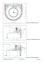
 Remove and inspect H.T. electrode and flame probe, 

ensure they are free from debris or deposits. – See 
Figures 10.2. 10.2.1 & 10.2.2 


8) 

Check the burner and clean using a soft brush if 

required (if possible use a vacuum cleaner to remove 
the dust from inside the burner tube). After cleaning the 
inside, the burner tube can be washed using a soapy 
water solution. Tap the burner flange firmly downwards 
on a block of wood to dislodge any residual debris from 
inside the burner tube. A damaged or cracked burner 
should be replaced.


Note:- 

Do not use a wire brush to clean the burner. 


9) 

Carefully remove the insulation pad from the heat 

exchanger back plate (accessed through the burner 
cavity) and replace with a new pad ensuring the edges 
are ‘tucked in’ to the gap past the last section 


10)

 Separate the gas valve / venturi from the fan inlet 

noting it’s orientation and inspect the fan scroll and 
impellor, clean and check for damage. 


11)

 Clean and check the venturi for contamination. 


12) 

Remove the fan/burner duct cover plate and inspect 

the non return valve in the duct for smooth operation.  


13)

 Separate the inlet flange /elbow fitting from the gas 

control valve by removing the 4 M5 socket cap head 
screws. Check that the mesh inlet filter in the gas valve 
is clear of debris, remove any foreign objects caught in 
the filter. 
Re-assemble in reverse order taking care to inspect and 
if necessary, replace any o-rings, gaskets or seals.


Refer to

 Section 8, Commissioning and Testing

, and 

test all gas joints broken or disturbed for soundness 
before firing. 
Carry out a combustion check by testing the flue gas 
CO

2

 and CO levels as detailed in 

Section 8.2.


10.3  Four Year Service 


Repeat the annual service as previously described but 
do not refit any components to the heat exchanger. 


10.3.1 

To clean the heat exchanger, the use of a high 

pressure water hose (40-80 psi) is recommended for 
the primary flue gas path. However provision must be 
made for the drainage of water used in this process. 
Remove the base plate to provide access to the pump. 
At the front of the boiler  remove the condensate drain 
trap assembly from the flue elbow. Connect a hose 
(32mm id.) To the flue elbow and take to a suitable drain 
or receptacle. The cleaning water and any debris will 
exit the sump through this opening.  


To clean the condensing flue gas path, isolate the boiler 
from the heating system and drain the boiler heat 
exchanger  using the drain valve provided in the return 
pipe. Disconnect the electrical supply to the pump, 
return sensor and the flow switch. Carefully support the 
pump, disconnect the unions and remove the pump. 
Remove the 2 M6 screws securing the return elbow /
pipe assembly to the heat exchanger and carefully 
remove the assembly. 
Remove the screws securing the plastic sump to the 
heat exchanger sealing plate and withdraw the sump 
down, disengaging the flue pipe from the flue elbow. 
The heat exchanger fin matrix is now accessible and 
the flue ways can be cleaned using a 25mm wide * 

Summary of Contents for F100W

Page 1: ...rs for Heating Domestic Hot Water Installations Installation Commissioning and Operating Instructions Models F40W F50W F60W F70W F85W F100W F125W F150W NATURAL GAS I2H IMPORTANT NOTE THESE INSTRUCTION...

Page 2: ......

Page 3: ...ILY I2H PLEASE ENSURE RELEVANT INFORMATION REQUIRED WITHIN DOCUMENT IS FOUND BEFORE FIRING BOILER COUNTRY OF DESTINATION UNITED KINGDOM REPUBLIC OF IRELAND THIS BOILER COMPLIES WITH ALL RELEVANT EUROP...

Page 4: ...5 0 BOILER ASSEMBLY 19 5 1 General 5 2 Water Connections 5 3 Flue Connections 5 4 Electrical Connections 6 0 PRE COMMISSIONING 20 6 1 Gas Supply 6 2 Ventilation 6 3 Pipework Valves and Pump 6 4 Flue 6...

Page 5: ...terminal locations 12 Figure 4 4 Water connections 13 Figure 4 5 1 Boiler condensate connection 16 Figure 4 5 2 Boiler condensate discharge 17 Figure 4 6 Wiring schematic 18 Figure 7 1 Gas system lea...

Page 6: ...58 Figure C5 1 Cascade flue 150kW 58 Figure C5 2 Cascade flue 150kW 59 Figure C6 1 Individual flue lengths C13 59 Figure C6 2 Individual flue lengths C13 59 Figure C6 3 Individual flue lengths C33 60...

Page 7: ...l and Industrial premises or large residential properties It may also be used to supply hot water for these premises via an indirect cylinder 1 3 4 The Fleet has a low water content and is fitted with...

Page 8: ...boiler must be kept upright during handling Care must be exercised to avoid toppling the boiler as this will result in damage The flue system is supplied separately to the boiler and must be specified...

Page 9: ...me Set and Pipe work Header Kits Where pipe work kits are supplied these are packaged separately from the boilers All ancillary items such as isolation valves and boiler make up connectors are factory...

Page 10: ...ngement showing frame flue header water pipework and low loss header Figure 2 5 Two boiler arrangement showing frame flue header water pipework and 6 port multi secondary circuit low loss header Open...

Page 11: ...he flue system allowing for sufficient access at sides and below boiler for pipework connections See Figure 3 1 Figure 3 1 1 Dimensions for individual flues refer to table Figure 3 1 3 Side View Side...

Page 12: ...an be adapted to 100 150 or split into a twin duct system C kits are available to adapt the flue ducts to 100 130 or 150mm depending upon the length of flue C F40 50W Dim F60 70W F85 100W F125W F150W...

Page 13: ...is designed to provide a compact solution for connecting the boilers to the gas supply and flow and return water connections Refer to kit instructions for specific information 440 410 Wall Mounting Pl...

Page 14: ...2 5 Figure 3 2 3 Optional Low Loss Headers Refer to table 3 2 5 Flow Return 507 380 190 180 Nom 190 Nom Flow Return 507 190 190 490 190 190 190 180 Nom 180 Nom Single secondary circuit Three secondar...

Page 15: ...Four boilers Refer to table Figure 3 2 4 Three boilers Refer to table 3 2 5 Dimension F40 100W F125 150W A mm 233 304 B DN50 PN16 DN65 PN16 Boiler C R 1 R2 1680 540 2090 20 540 215 85 1850 Nom 2170 No...

Page 16: ...ce with BS 6644 The plant room must have sufficient space for installation of boilers pipe work pumps controls flues ventilation access and servicing and other items of plant 4 2 Gas Supply Gas supply...

Page 17: ...Any stabiliser fitted must be in or close to the vertical chimney Due to the low flue gas temperature 50 C condensation will occur in the flue flue materials must be non corrosive and utilise fully se...

Page 18: ...Above an opening air brick opening window etc 300 C Horizontally to an opening air brick opening window etc 300 D Below gutters soil pipes or drain pipes 75 E Below eaves 200 F Below balconies or car...

Page 19: ...ent that the system design pressure is lower than the boiler maximum operating pressure according to the requirements of BS6644 2011 The Fleet boiler has an aluminium heat exchanger It is a requiremen...

Page 20: ...tenance is carried out by Hamworthy Heating Limited or a competent maintenance company the maintenance regime detail shall be provided in writing when required to prove compliance with the operating a...

Page 21: ...ntifreeze plus protection agent Fernox Restorer cleaning agent for removing rust lime and sludge Protector protection agent F1 protection agent The following applies to system design In order to avoid...

Page 22: ...ly before the connection of the flue system to the boiler and taken to drain Condense is mildly acidic typically pH3 pH5 Condense pipe work must be non corrosive and not copper Hamworthy recommend pla...

Page 23: ...ndensate Connection and discharge Concentric inline drain trap Concentric inline drain trap Single pipe inline drain trap Tundish to drain Horizontal Concentric Flue System Vertical Concentric Flue Sy...

Page 24: ...modules stop start circuit 24V DC Any interlock circuit must be in series with the time control for each circuit The interlock circuit must never be used to isolate the boiler electrical supply ADDITI...

Page 25: ...ust be taken to ensure that undue stress is avoided on the boiler flow and return connections It is recommended that unions are fitted local to the boiler and outside of the casing to permit future se...

Page 26: ...m of 150 kW may be terminated with horizontal flue discharges Equivalent lengths for 90 bends and 45 bends are given in Appendix C 5 4 Electrical Connections The following electrical connections are p...

Page 27: ...o drain Heat load is available 6 4 Flue Ensure that Flue system is correctly designed and installed to suit boilers Flue passages to chimney are clear 6 5 Electrical Ensure that Electrical connections...

Page 28: ...a single speed circulating pump and flow is controlled through a balancing valve which must be checked and set during commissioning As a safety precaution a flow switch is fitted to the boiler heat e...

Page 29: ...namic reading The dynamic reading cannot be taken until the boiler has been started refer to 7 4 A maximum difference in gas pressure of 1 mbar must not be exceeded between static and dynamic conditio...

Page 30: ...valve The boiler should shutdown after approximately one second and attempt a re ignition Check that the flame has been extinguished 2 Alternatively the flame probe lead can be removed from the end o...

Page 31: ...ffset Models F40W F50W F60W F70W Models F85W F100W F125W F150W 4 If combustion is outside of the ranges defined below the factory sealed valves may be adjusted using the following procedure High Fire...

Page 32: ...ntrols the flow through the boiler Using the boiler flow and return temperature sensors visible on the display via the LMU programme This MUST be carried out with the boiler running at maximum firing...

Page 33: ...supervision active too little flow through boiler 7 8 User Instructions When the boiler is fully commissioned the owner or their representative should be made aware of the lighting up and operating in...

Page 34: ...ral Overview of Boiler Controls Low Gas Pressure Switch Overheat Thermostat HT Spark Generator Combustion Fan Air Pressure Switch Fuse Water Flow Switch 230v Mains Supply IEC Mains Outlet LMU Control...

Page 35: ...refer to figure 8 2 1 1 A change on the information level can be made at any time by pressing the Info button Additional pushes of the Info button will deliver the following data sequence provided by...

Page 36: ...M C 4 RelModLevel Relative output C 5 Pumpe_PWM Pump setpoint PWM Not used C 6 ek0 Control differential C 7 C8 C9 Reserved Setpoints Service level d 0 Reserved d 1 Tsoll Setpoint of 2 position or modu...

Page 37: ...HAMWORTHY HEATING LTD 31 FLEET W series 500001211 F Figure 8 2 1 3 Operation and display philosophy...

Page 38: ...g of symbols Display of dhw temperature or dhw heating active not used Display of boiler or room temp set point or space heating active Display of outside temperature Operational level Normal Operatio...

Page 39: ...t display If no button is pressed for about 8 minutes the screen will automatically return to the default display Figure 8 2 3 2 Display of Status Code When a status code is displayed the display 1 sh...

Page 40: ...2 4 Display of lockout code 304 7494z35 0202 8 2 5 Adjusting the heating circuit setpoint temperature Press the flow temperature button to adjust the heating circuit setpoint Press to adjust the requi...

Page 41: ...Time program HK1 heating circuit 1 11 Time program HC1 switch on time 1st period 00 00 24 00 hh mm 10 min 06 00 12 Time program HC1 switch off time 1st period 00 00 24 00 hh mm 10 min 22 00 13 Time pr...

Page 42: ...Heating circuit operating modes The control provides 4 different heating circuit operating modes for LMU heating circuit 1 They can be directly selected depending on the requirements see figure 8 2 9...

Page 43: ...the return sensor provide overheat protection as follows If the first level temperature is exceeded a fault code is displayed If the second level temperature is exceeded an alarm code is displayed an...

Page 44: ...the boiler to cool and reset thermostat Investigate cause of overheating see section 9 3 113 Flue gas supervision equipment has cut out 117 Water pressure too high 118 Water pressure too low 119 Wate...

Page 45: ...ure required to raise the maximum operating temperature possible from the individual boiler modules As standard the boiler modules leave the factory with a maximum operating temperature of 85 C Where...

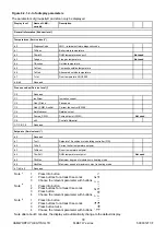
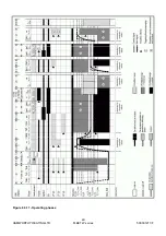
Page 46: ...HAMWORTHY HEATING LTD 40 FLEET W series 500001211 F Figure 8 3 11 Operating phases...

Page 47: ..._TSA1_2 PH_TSA2_2 10 Heating operation PH_TI PH_MODULATION Heating mode 11 DHW operation PH_TI PH_MODULATION DHW mode 12 Parallel operation of space heating and DHW heating PH_TI PH_MODULATION Heating...

Page 48: ...e operation of the flow switch can be checked by closing one of the isolating valves connecting the boiler to the system this will generate error E164 on the LMU display 9 3 Ignition Controller 1 The...

Page 49: ...A DISPLAY KEYPAD MODULE FLAME IONISATION PROBE 2 1 1 3 230V 0V HT 1 2 1 3 C 1 2 HT ELECTRODE GAS VALVE SPARK GENERATOR SAFETY LIMIT THERMOSTAT 2 3 L N N L 3 2 1 1 DC FAN PUMP 2 3 3 2 1 1 BLUE BROWN BL...

Page 50: ...ner tube After cleaning the inside the burner tube can be washed using a soapy water solution Tap the burner flange firmly downwards on a block of wood to dislodge any residual debris from inside the...

Page 51: ...HAMWORTHY HEATING LTD 45 FLEET W series 500001211 F Figure 10 2 Combustion Chamber A A B B Figure 10 2 1 Spark Electrode position Figure 10 2 2 Flame Probe position...

Page 52: ...sensor is located in the flue elbow Prior to removal check the resistance of the sensor against Figure B 1 3 In refitting the sensor a sealant will be required on the threads Check for soundness of th...

Page 53: ...ical control panel which is secured to the boiler chassis by 2 spring latches Pull the panel forward to disengage the latches If a clip in module is fitted this must be removed and transferred to the...

Page 54: ...ication F150W 533301034 Gas Control Valve F40W F70W 533903040 Gas Control Valve O ring F40W F70W 531299051 Gas Control Valve F85W F150W 533903044 Gas Control Valve O ring F85W F150W 742111245 Combusti...

Page 55: ...0 50 60 70 Boiler Output kW maximum non condensing 80 60 C kW 36 1 45 1 54 1 63 2 Boiler Output minimum 80 60 C kW 7 2 9 0 10 8 12 6 F85W F100W F125W F150W Boiler Input maximum kW Gross 87 2 102 6 128...

Page 56: ...ly should only serve the boiler 4 Multiple modules It is highly recommended that each boiler is connected via its own mains isolator to facilitate servicing and maintenance of the individual boiler wh...

Page 57: ...21 22 21 22 21 22 15 16 15 16 15 16 External Control Optional External Control Boiler 1 Terminal Rail Boiler 2 Terminal Rail Boiler 3 Terminal Rail 0 10V 0 10V 0 10V Control Signal 0 10V or Enable Not...

Page 58: ...4 145 0 206 10 0 55047 70 0 1753 150 0 183 5 0 42158 75 0 1481 155 0 163 0 0 32555 80 0 1256 160 0 145 5 0 25339 85 0 1070 165 0 130 10 0 19873 90 0 915 170 0 117 15 0 15699 95 0 786 175 0 105 20 0 12...

Page 59: ...Any flue system with a horizontal section should have a maximum slope of 3 upwards in the direction of the exhaust gas flow All joints should be such that any condensation is directed back down the s...

Page 60: ...er size consideration should be given to the fitting of a flue discharge terminal or grille to stop ingress of birds etc C1 7 Surface Temperatures Combustible materials in the vicinity of the boiler a...

Page 61: ...Max L 45 90 cond Drain 40 100 150 60 0 5 0 75 0 5 50 100 150 40 0 5 0 75 0 5 60 100 150 30 0 75 1 0 5 70 100 150 20 0 75 1 0 5 85 100 150 15 0 75 1 0 5 100 100 150 10 1 1 5 0 75 125 100 150 7 1 1 5 0...

Page 62: ...2 1 Room sealed concentric C33 vertical flue system Figure C1 2 Room sealed concentric C13 horizontal flue system 580 min 80 125 930 min 100 150 1350 80 125 1730 100 150 600 min 30mm m fall to boiler...

Page 63: ...cond Drain 40 100 150 60 0 5 0 75 0 5 50 100 150 40 0 5 0 75 0 5 60 100 150 30 0 75 1 0 5 70 100 150 20 0 75 1 0 5 85 100 150 15 0 75 1 0 5 100 100 150 10 1 1 5 0 75 125 100 150 7 1 1 5 0 75 150 100 1...

Page 64: ...Part no 562511045 Op ons 100 87 Elbow 532511115 100 45 Elbow 532511114 100 1m 532511130 100 2m 532511131 Model Flue size Equivalent lengths m Max L 45 90 cond Drain 40 100 100 0 5 0 75 0 5 50 100 50...

Page 65: ...ue size Equivalent lengths m Max L 45 90 cond Drain 40 130 100 0 5 0 75 0 5 50 130 100 0 5 0 75 0 5 60 130 100 0 5 0 75 0 5 70 130 100 0 5 0 75 0 5 85 130 100 0 75 1 0 5 100 130 100 1 1 5 0 75 125 130...

Page 66: ...1 Cascade flue system Figure C4 2 B23 Open flue system 560 crs 600 min 520 max 300 600 min 580 min 80 125 930 min 100 150 1350 80 125 1730 100 150 Boiler connection kit see note previous page Note Hor...

Page 67: ...0 Flue Header Flue Header Equivalent lengths m Load kW Size mm Max L 45 90 80 150 100 3 4 100 150 100 3 4 150 150 100 3 4 200 150 60 3 4 250 150 35 3 4 300 150 10 3 4 300 200 95 3 4 400 200 45 3 4 500...

Page 68: ...87 Elbow 532511169 250 1m straight 532511137 250 roof terminal Not HHL supply Cascade flue kit 40 100kW 150 HHL Part no 562511020 Op ons 150 87 Elbow 532511122 150 45 Elbow 532511121 150 1m straight...

Page 69: ...entilation is required which must communicate direct to outside for cooling purposes Low level inlet 10cm per kW of total rated input Net High level output 5cm per kW of total rated input Net D1 2 2 A...

Page 70: ...iler house shall be as follows At floor level or 100mm above floor level 25 C At mid level 1 5m above floor level 32 C At ceiling level or 100mm below ceiling level 40 C D 1 5 General Requirements The...

Page 71: ...e secondary circuits to be connected to the header Figure E1 1 1 on the following page show typical layouts 5 Ideally individual valves should be fitted to each module to enable isolation from the sys...

Page 72: ...w the boiler is fitted with an integral flow switch Particular attention should be paid to the restriction of external flow circuits during periods of low heat demand Each boiler module is fitted with...

Page 73: ...ble valve check Expansion Air Vent Automatic Valve Drain valve valve Drain Boiler Output Feed mm Vent mm 60 150kW 25 32 150 300 kW 32 38 300 600 kW 38 50 601 KW 50 65 Figure E1 4 Cold Feed and Vent Pi...

Page 74: ...ral pump performance curves 0 1 1 2 2 3 3 4 5 Q m h 3 Model F 40W F 50W F 60W F 70W Model F 85W F 100W F 125W Model F 150W 0 4 1 0 0 2 0 3 0 4 0 5 0 6 0 1 2 2 0 2 8 3 6 4 4 Head m Head m Head m 6 0 6...

Page 75: ...uits Typical layout for primary circuit with low loss header Typical layout for primary circuit with plate heat exchanger separation of secondary circuits AAV AAV AAV AAV Drain Drain Drain Drain Drain...

Page 76: ...hold both up and down arrow keys for at least five seconds to enter advanced parameter list H90 displayed top right of HMI screen Use either up or down arrow key to scroll through the parameter list a...

Page 77: ...1 F Option 2 for use with the QAA73 programmable room unit To enable an additional mixing circuit with use of AGU 2 500 change the setting by using the or key and set value to 50 Press mode button to...

Page 78: ...HAMWORTHY HEATING LTD 72 FLEET W series 500001211 F INSTALLER SITE ADDRESS BOILER TYPE BOILER SIZE S UNIT NO S SERIAL NO S FLUE USEFUL USER INFORMATION...

Page 79: ...Please complete the information on the Registration card cut out and return to Hamworthy Heating Ltd...

Page 80: ......

Page 81: ......

Page 82: ...1030 fax 0151 647 8101 Southern Ireland Sales Service HEVAC Limited Naas Road Dublin 12 Ireland tel 00 353 141 91919 fax 00 353 145 84806 Northern Ireland Sales Service HVAC Supplies Limited Unit A6 D...

Reviews: