background image

IMPORTANT NOTE

THESE INSTRUCTIONS MUST BE READ 

AND UNDERSTOOD BEFORE INSTALLING,

COMMISSIONING, OPERATING OR 

SERVICING EQUIPMENT

MARSHALL HE 


BOILER SEQUENCE CONTROL PANEL  


INSTALLATION, COMMISSIONING AND 

MAINTENANCE INSTRUCTIONS


Summary of Contents for MARSHALL HE

Page 1: ...TE THESE INSTRUCTIONS MUST BE READ AND UNDERSTOOD BEFORE INSTALLING COMMISSIONING OPERATING OR SERVICING EQUIPMENT MARSHALL HE BOILER SEQUENCE CONTROL PANEL INSTALLATION COMMISSIONING AND MAINTENANCE...

Page 2: ...ating safely and efficiently Maintenance Agreements 01202 662555 Regular routine servicing of equipment by Hamworthy service engineers inspects the safety and integrity of the plant reducing the risk...

Page 3: ...NSTALL COMMISSION OR OPERATE THE MARSHALL HE SYSTEM THE MARSHALL HE SYSTEM IS INTENDED FOR USE ONLY IN COMMERCIAL LIGHT INDUSTRIAL APPLICATIONS THIS BOILER SEQUENCE CONTROL SYSTEM COMPLIES WITH THE ES...

Page 4: ...4 1 Controller Location 4 2 Electrical Connections 4 3 Control Inputs Connections 4 4 Temperature Sensors 4 5 Completion 5 0 COMMISSIONING 6 5 1 Pre Commissioning Checks 5 2 Programming 5 3 Marshall H...

Page 5: ...he outside air temperature falls the heat loss from a building increases so to compensate for this the Marshall HE controller will increase the water flow temperature thus increasing the heat input to...

Page 6: ...ctive mode This is indicated on the controller s system information screen refer to section 1 0 Run Mode Display Screens of the Marshall HE Users Operating Instructions HHL No 500001066 The heating ci...

Page 7: ...ion Operation Refer to section 2 0 Run Mode Functions of the Marshall HE User s Instructions for details of the operation of the override functions are switched off The circulation pump overrun functi...

Page 8: ...closure by inserting a small flat bladed screwdriver into the slot and twisting Unscrew and retain the four screws exposed The front half of the enclosure can then be lifted off carefully disconnect t...

Page 9: ...d to insulate the shield conductor to prevent the possibility of it contacting the other conductors or any of the sensor or controller pcb components The flow and external sensor housings incorporate...

Page 10: ...Note Wiring MUST be checked by a suitably competent person 5 1 3 Check the external timeclock remote override switch remote holiday override switch and safety interlock circuit connections as applicab...

Page 11: ...press the PROG key and the code entry screen will be displayed A SECURITY CODE IS REQUIRED TO PROGRAM THIS UNIT Please enter the code 2 Enter the four digit code using the numerical keypad The code en...

Page 12: ...1 until the sensor reading is correct Enter calibration setting Number 1 16 THE SENSOR IS NOW READING 21 C 3 Press ENTER to enter the new setting The number 2 sensor calibration setting screen is dis...

Page 13: ...tting in the Marshall HE Users Operating Instructions Enter the temperature offset upper limit you want from the UP button 04 11 Press the ENTER key to enter the new setting and display the lower temp...

Page 14: ...n of on off and high low boilers are installed enter the appropriate high low figure but note that the high low boilers must be first in the firing sequence Note The Marshall HE controller will only p...

Page 15: ...erical keypad to enter the outside air temperature in C at which the heating system is to shut down A setting of 00 will disable this function Enter the External temperature that you want the heating...

Page 16: ...o Optimizing 00 32 Use the numerical keypad to enter the optimiser rate of change ratio in minutes C This setting is used to de termine the heating start time see Section 3 3 Optimiser Function Operat...

Page 17: ...Each increase of 1 of this setting will reduce the com pensated flow temperature by 1 C Enter the COMPENSATION OFFSET NUMBER 10 NORMAL 10 39 Press the ENTER key to enter the new setting and the compe...

Page 18: ...ater flow temperature in C Enter the MAXIMUM FLOW temperature for the boiler 82 45 Press the ENTER key to enter the new setting and display the pump overrun setting screen Enter the PUMP OVERRUN TIME...

Page 19: ...want the lead boiler to shift once a week 01 or be fixed 00 01 52 Use the numerical keypad to select 01 for the weekly lead boiler shift or 00 for the fixed boiler sequence Note If a combination of h...

Page 20: ...it is switched on and off 5 3 6 When these checks have been carried out enter the settings into the Marshall HE Control Settings table in Figure 12 Page 28 5 3 7 The Marshall HE system should now be d...

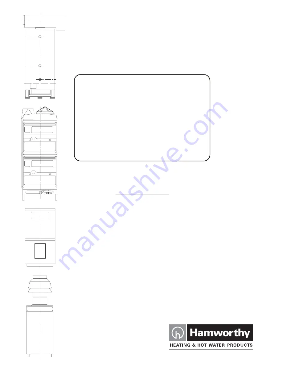
Page 21: ...HAMWORTHY HEATING LTD Page 500001065 B MARSHALL HE 17 Figure 2 Overall Dimensions...

Page 22: ...HAMWORTHY HEATING LTD Page 500001065 B MARSHALL HE 18 Figure 4 Marshall HE System Schematic...

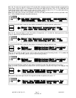
Page 23: ...HAMWORTHY HEATING LTD Page 500001065 B MARSHALL HE 19 Figure 5 Site Wiring Connection Details...

Page 24: ...HAMWORTHY HEATING LTD Page 500001065 B MARSHALL HE 20 Figure 6 Example Boiler Connection Schemes...

Page 25: ...r 164 110 17 BSP PARALLEL POCKET 20mm CABLE GLAND OR CONDUIT CONNECTION 11 DIMENSIONS BSP TAPPING END OF PROBE ON PIPE CENTRE LINE OUTLET OF FLOW HEADER OUTLET OF FLOW HEADER PROBE CENTRE AXIS ALIGNED...

Page 26: ...FIXING POINTS SENSING POINT OUTLET OF FLOW HEADER CUT STRAP TO CORRECT LENGTH AND SCREW IN FASTENING HOOKS ENSURE A FIRM AND CLEAN CONTACT BETWEEN THE SENSOR AND THE SURFACE OF THE FLOW HEADER NOTE ME...

Page 27: ...HALL HE 23 Figure 9 External Sensor 20mm CABLE GLAND OR CONDUIT CONNECTION NOTE A CABLE GLAND OR CONDUIT CONNECTOR MUST BE UTILISED TO ENSURE A WATER TIGHT INSTALLATION 37 60 49 CTRS COVER REMOVED 17...

Page 28: ...e 500001065 B MARSHALL HE 24 Figure 10 Room Sensor 61 CTRS NOTE WHEN MOUNTING DIRECTLY TO A WALL COUNTERSUNK SCREWS MUST BE USED 2 OFF SLOTTED MOUNTING HOLES 4 2 x 10 LONG KNOCKOUT HOLE FOR CABLE ENTR...

Page 29: ...offset setting 15 offset setting 10 offset setting 5 offset setting 0 offset setting Compensation Slope Offset Setting with slope set at 3 to 1 and maximum flow temperature set at 95 C Outside Air Te...

Page 30: ...e Flow 05 Holiday Function Setting Internal External 00 Internal Only 01 External Only 02 or None 03 Summer Shutdown Setting C Optimiser Setting Optimiser 00 Timer 01 or Fixed Optimiser 02 Fixed Flow...

Page 31: ...y override pe riod is in force Delete the holiday period refer to section 3 5 of the Marshall HE User s Instructions The Marshall HE has been manu ally overridden to holiday mode Reset the manual holi...

Page 32: ...higher value Reset to correct value refer to sec tion 2 3 of the Marshall HE User s Instructions Room temperature sensor fault if fitted sensor reads Check the room sensor wiring con nections at the...

Page 33: ...HAMWORTHY HEATING LTD Page 500001065 B MARSHALL HE 29 NOTES...

Page 34: ...HAMWORTHY HEATING LTD Page 500001065 B MARSHALL HE 30 NOTES...

Page 35: ...Notes...

Page 36: ...y reserves the right to make changes and improvements which may necessitate alteration to the specification without prior notice Connect direct Direct Dial Telephone and Fax Numbers Direct Email Addre...

Reviews: