


HAMWORTHY HEATING LTD Page 500001065/B
MARSHALL HE
13
36)
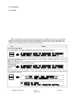
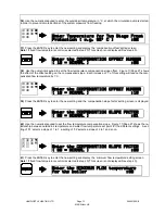
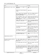
Use the numerical keypad to enter the outside air temperature, in
°
C, at which the circulation pump is started,
in order to prevent remote sections of the system pipework from freezing.
Enter Temperature for Two Stage Frost
Protection ( e.g. 02' C ) :02
37)
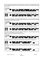
Press the ENTER key to enter the new setting and display the `compensation offset' setting screen.
Note!
If fixed flow temperature control is selected in step 20) This screen is not displayed. See step 45).
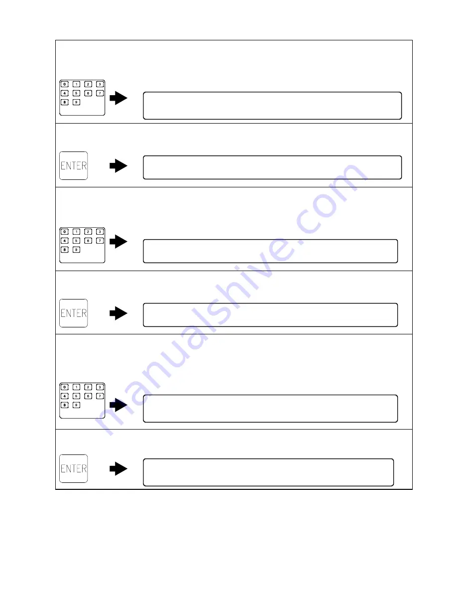
Enter the COMPENSATION OFFSET NUMBER
( 10 = NORMAL ) :00
38)
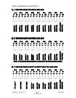
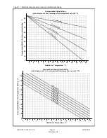
Use the numerical keypad to set the flow temperature compensation slope offset. Figure 11/Page 27 shows
the effect of the offset setting on the compensation slope. Each increase of ‘1' of this setting will reduce the com-
pensated flow temperature by 1
°
C.
Enter the COMPENSATION OFFSET NUMBER
( 10 = NORMAL ) :10
39)
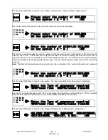
Press the ENTER key to enter the new setting and the ‘compensation slope factor’ setting screen is displayed.
Enter the COMPENSATION SLOPE FACTOR
( 03 = NORMAL ) :01
40)
Use the numerical keypad to set the flow temperature compensation slope. Figure 11/Page 27 shows the re-
lationship between outside air temperature and water flow temperature set point for the different settings. A set-
ting of ‘01' selects a slope of 1 to 1, a setting of ‘02' selects a slope of 2 to 1 and so on.
Enter the COMPENSATION SLOPE FACTOR
( 03 = NORMAL ) :03
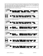
Enter the MINIMUM FLOW temperature
for the boiler :00
41)
Press the ENTER key to enter the new setting and display the `minimum flow temperature' setting screen.
Note!
If fixed flow temperature control is selected in step 20) This screen is not displayed. See step 45).
Summary of Contents for MARSHALL HE
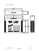
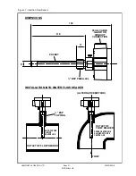
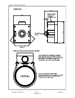
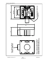
Page 21: ...HAMWORTHY HEATING LTD Page 500001065 B MARSHALL HE 17 Figure 2 Overall Dimensions...
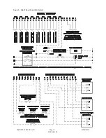
Page 22: ...HAMWORTHY HEATING LTD Page 500001065 B MARSHALL HE 18 Figure 4 Marshall HE System Schematic...
Page 23: ...HAMWORTHY HEATING LTD Page 500001065 B MARSHALL HE 19 Figure 5 Site Wiring Connection Details...
Page 33: ...HAMWORTHY HEATING LTD Page 500001065 B MARSHALL HE 29 NOTES...
Page 34: ...HAMWORTHY HEATING LTD Page 500001065 B MARSHALL HE 30 NOTES...
Page 35: ...Notes...


