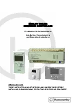
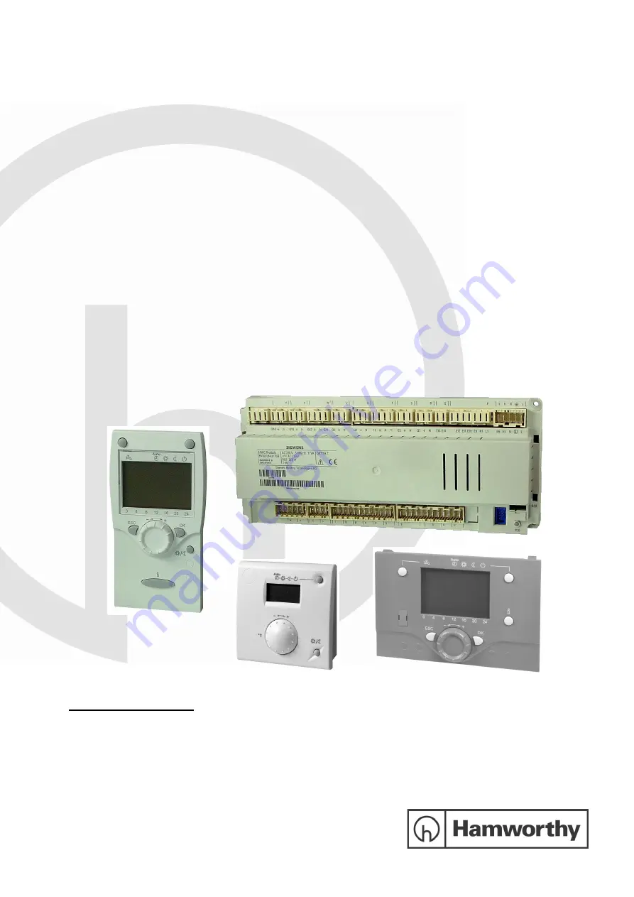
Hamworthy Merley, Installation, Commissioning And Operating Instructions
The Hamworthy Merley product comes with detailed Installation, Commissioning, and Operating Instructions manual for easy setup and use. You can download the manual for free from 88.208.23.73:8080, ensuring you have all the necessary information to maximize the efficiency of your product.
Share
Download


Reviews:
No comments
Related manuals for Merley

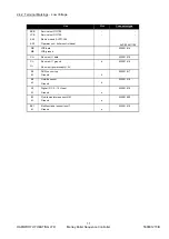
20
Brand: J4C Pages: 4

20
Brand: Vacon Pages: 62

ControlMaster CM15
Brand: ABB Pages: 28

650 series
Brand: ABB Pages: 128

ACS880 Series
Brand: ABB Pages: 50

ABILITY SSC600
Brand: ABB Pages: 42

AC 800M
Brand: ABB Pages: 120

ACH400 Series
Brand: ABB Pages: 28

TZIDC-110
Brand: ABB Pages: 59

ACS355 series
Brand: ABB Pages: 139

LME620-AI
Brand: ABB Pages: 15

PST30
Brand: ABB Pages: 10

LME620-AI
Brand: ABB Pages: 30

LME620-AI
Brand: ABB Pages: 44

XFC G5
Brand: ABB Pages: 2

ControlMaster CM15
Brand: ABB Pages: 4

Leroy-Somer R180
Brand: Nidec Pages: 20

5800 Series
Brand: S&C Pages: 34


