HAMWORTHY HEATING LTD
6
PUREWELL
Vari
Heat c
500001169/T
4.0 SITE LOCATION AND PREPARATION
4.1 Site Location.
The floor or plinth for the boilers and water manifold kit must be both flat and level to
ensure correct alignment of fittings and connections.
The floor or plinth must be sufficiently strong to support the weight of both the boilers
and manifold kit where used.
The floor or plinth must be fireproof in accordance with BS 6644.
The plantroom must have sufficient space for installation of boilers, manifold kits,
pipework, pumps controls, flues ventilation, access and servicing and other items of
plant.
4.2 Gas Supply.
Gas supply pipes must be in accordance with BS 6891 or IGE/UP/2
Gas supply connection to the boiler must not be smaller than the connection on the
boiler - R1”
Gas installation must be soundness tested to BS 6891 or IGE/UP/1 & IGE/UP/1A.
Gas installation must be purged to BS 6891 or IGE/UP/1 & IGE/UP/1A.
Inlet gas pressure to boiler should be nominal 20mbar (minimum 17.5mbar) dynamic at
the connection to the boiler.
Boiler house gas isolation valve must be clearly identified and installed close to the
entrance / exit.
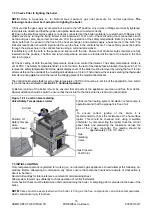
R 1” Gas Connection
Figure 4.2 – Gas Connection Point
Summary of Contents for Purewell VariHeat 70c
Page 2: ......
Page 43: ...HAMWORTHY HEATING LTD 37 PUREWELL VariHeat c 500001169 T Figure 8 3 11 Operating phases ...
Page 44: ...HAMWORTHY HEATING LTD 38 PUREWELL VariHeat c 500001169 T Figure 9 0 Boiler Wiring Schematic ...
Page 65: ...HAMWORTHY HEATING LTD 59 PUREWELL VariHeat c 500001169 T Figure E1 2 Typical Piping Layouts ...
Page 70: ...HAMWORTHY HEATING LTD 64 PUREWELL VariHeat c 500001169 T NOTES ...
Page 71: ......


