background image


HAMWORTHY HEATING LTD 


25 

PUREWELL VariHeat he 


500001155/F 

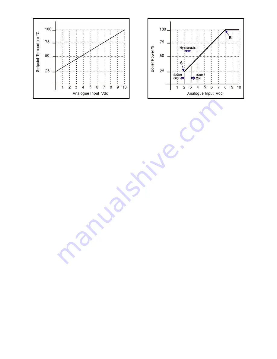
Figure 8.5.3.2 - Power Control 

Figure 8.5.3.1 - Flow Temperature Control 

8.5.4   

Central Heating Program 

To activate this mode of demand, the relevant parameter must be set to Remote On/Off or Switched Live On/Off. 
The central heating demand is detected when the Room Thermostat or Switched Live input closes. If an outside 
sensor is fitted, the water temperature setpoint depends on the outside sensor value and the selected heating 
curve ( to be set during commissioning). 
Modulation during this mode of operation is based upon the measurement of flow sensor S1. The selected heat-
ing curve will determine the control setpoint. The user can limit the maximum setpoint. 
If the outside sensor is not connected, the setpoint is determined by the user. 
If the outside air temperature exceeds 32°C the demand is switched OFF, and will be re-instated when the outside 
temperature has dropped by the hysteresis setting –see figure 8.5.4. 
As soon as the flow temperature exceeds the setpoint by the hysteresis value, the burner will switch OFF, the 
pump will continue to run and the anti-cycling timer will start. As soon as the flow temperature has dropped below 
the hysteresis value and the anti-cycling timer has elapsed, the burner will switch ON. 
The regulation is based upon PI -control, but the maximum capacity of the boiler can be limited by step modula-
tion - refer to section 8.5.7.3.


8.5.5  

Frost Protection 

Individual boilers are capable of two stage frost protection by setting the relevant parameters. 
If the return temperature (sensor S2) drops below the first level protection temperature, the pump is activated. If 
the temperature continues to fall below second level protection temperature, the burner is switched ON and the 
fan speed is held at minimum firing rate. The pump and the burner remain ON until the temperature rises above 
the temperature On Offset. 
Should an outside sensor be fitted, by setting the relevant parameters, the pump is switched ON if the outside 
temperature is below the minimum frost setting, and it will switch OFF outside of the Hysteresis band. 
Should the boiler be switched OFF on the display screen, the frost protection function is still active. 

Note: 

- Frost protection is 

only

 available on the Shunt Pump. 

8.5.6  

Stand-by 

Logging data - the control will log data to provide information for both User and Service Engineer. This logged 
data can be used to correct an error or block and consists of: 

• 

Total gas consumption 

• 

Running hours, with power equal to or less than 50% of its maximum setting. 

• 

Running hours with power greater than 50% of its maximum setting. 

• 

Total ignition attempts 

• 

Fault ignition 

• 

Last 10 errors/blocks 

Summary of Contents for PUREWELL VariHeat he

Page 1: ...IMPORTANT NOTE THESE INSTRUCTIONS MUST BE READ AND UNDERSTOOD BEFORE INSTALLING COMMISSIONING OPERATING OR SERVICING EQUIPMENT...

Page 2: ...IS FOR USE ON GROUP H NATURAL GAS 2ND FAMILY I2H PLEASE ENSURE RELEVANT INFORMATION REQUIRED WITHIN DOCUMENT IS FOUND BEFORE FIRING BOILER THIS BOILER COMPLIES WITH ALL RELEVANT EUROPEAN DIRECTIVES PR...

Page 3: ...s Supply 6 2 Ventilation 6 3 Pipework Valves and Pump 6 4 Flue 6 5 Electrical 7 0 CHECKS PRIOR TO LIGHTING 14 7 1 Boiler Gas System Leak Check 7 2 Checks Prior to Lighting the Boiler 7 3 Initial Light...

Page 4: ...Display 15 Figure 7 3 2 Start Up Display Sequence 16 Figure 7 4 1 Removal of Sample Point Plug 17 Figure 7 4 2 Combustion Analyser Probe setting 17 Figure 7 4 3 Fan Assembly PV65he PV85he 18 Figure 7...

Page 5: ...pen Flue Natural Draught B23 Flue System 45 Figure D1 Mechanical Ventilation Flow Rates 47 Figure E1 Water Data 48 Figure E1 1 Cold Feed and Vent Pipe Sizes 48 Figure E1 2 Typical Piping Layouts 49 Fi...

Page 6: ...level water switch which protects the water pumps and will directly or indirectly shut down the boiler plant should a low water condition occur Consideration should also be given to the maximum worki...

Page 7: ...er is designed to pass through a standard doorway where access is restricted NOTE The boiler is supplied with cardboard corner protection and shrink wrapped for protection during handling However when...

Page 8: ...se provide details of your order such as order number and contract number as well as a detailed description of the missing item Reverse Return Header Sets Where reverse return header sets are used the...

Page 9: ...top or display covers See Figure 3 1 below 3 2 The Hamworthy Heating Ltd water manifold kit is designed to provide a compact solution for connecting the boilers to the gas supply and flow and return...

Page 10: ...ves are not required on each module and a common valve can be fitted in the combined flow pipe However each boiler has a Rp1 connection plugged in the rear of the boiler heat exchanger assembly for us...

Page 11: ...on of boilers manifold kits pipework pumps controls flues ventilation access and servicing and other items of plant 4 2 Gas Supply Gas supply pipes must be in accordance with BS 6891 or IGE UP 2 Gas s...

Page 12: ...sure and condense in flue Flue construction is recommended of a twin wall insulated type to maintain buoyancy within the flue Care should be taken to ensure that the flue system is installed in such a...

Page 13: ...stem pipework is flushed twice before water treatment In hard water areas precautions such as water treatment should be implemented to prevent the build up of sludge and scale Leaks in the system pipe...

Page 14: ...Condense may be discharged to a standard drain subject to National or Local regulations Boiler Condensate Connection 32mm o d Figure 4 5 1 Boiler Condensate Pipe Work Installation Figure 4 5 2 Positio...

Page 15: ...erve the boiler Where volt free contacts are used these too must be individually isolatable Time clock control should be via the boiler modules Remote On Off circuit 30V DC Any circuit connected to th...

Page 16: ...e is necessary 5 1 Flue Pipe So as to avoid damage the flue connecting pipe is supplied separately Fit the elbow to the base of the boiler and secure using the gasket and 4 M8 x 16 Hex Head Screws Moi...

Page 17: ...open to atmosphere Hamworthy Heating Ltd provide a connection on the boiler for the safety valve Where using Hamworthy Heating Ltd pipework kits assembly of these is detailed in the Instruction manual...

Page 18: ...Pipework and valve arrangement is installed to Hamworthy Heating recommendations Circulating system is full of water vented and pressurised appropriately Circulation pump is fitted working and interlo...

Page 19: ...the electrical power and gas to the appliance 2 By unscrewing screw at Position X of Figure 7 1 1 remove the red gas pressure switch L H S picture or loosen the test point valve plug R H S picture 3...

Page 20: ...on non domestic gas appliances should attempt the following operations Before attempting to commission any boiler ensure that personnel involved are aware of what action is about to be taken Record al...

Page 21: ...al Assessment The flame ionisation signal generated whilst the boiler is firing can be viewed directly from the display screen The value is set to read dc A Refer to 8 7 1 3 7 3 4 Adjusting the settin...

Page 22: ...operating correctly 8 Remove the combustion analyser probe replace the sample point plug in the front of the base of the boiler 9 If the combustion readings fall outside the required range DO NOT adj...

Page 23: ...Fan Assembly PV65he PV85he High Fire Gas Air Adjustment Factory Sealed Pressure Feed Back Tube Outlet Gas Pressure Test Point Low Fire Gas Adjustment Factory Sealed Pressure Switch Pressure Switch Lo...

Page 24: ...to 8 multiple boilers by selection of Master Slave configuration Note To ensure safe and reliable operation all wiring between sensors master slave boilers must be separated from mains voltage wiring...

Page 25: ...m EEPROM corrupted flash memory too many restarts after detecting a fault etc the control will lock up and nothing will work including reset with the display registering the last message The only way...

Page 26: ...lay a lock out To clear a lock out press the enter button to reset the boiler To access the service mode press the Exit Button for 5 seconds A four digit numerical code must be entered to enable the e...

Page 27: ...mperature and the desired set point calculated by the heat curve and User setting Should there be no mixed flow sensor fitted the Master will allow all Slaves to operate at maximum power Adjustment of...

Page 28: ...ler becomes less than Pdown then the last boiler switched on is switched off and the power divided between the firing boilers see figure 8 5 2 4 1 8 5 2 4 2 Boiler switching On Off The description abo...

Page 29: ...p is not provided by the Master 8 5 3 Boiler Management System This mode of operation relates to a 0 10V dc control signal from a BMS to individual boiler modules and by setting the relevant parameter...

Page 30: ...imer has elapsed the burner will switch ON The regulation is based upon PI control but the maximum capacity of the boiler can be limited by step modula tion refer to section 8 5 7 3 8 5 5 Frost Protec...

Page 31: ...perature at the start of the block 8 5 7 2 Control of flow temperature gradient The flow temperature gradient is activated by the following heat demand BMS based on temperature Remote On Off After swi...

Page 32: ...ure switch or low gas pressure switch will result in a block on all heat demands with corresponding message on the display screen 8 5 7 6 Fan Speed Control The fan will modulate to the setpoint determ...

Page 33: ...et by the relevant parameters 8 6 5 Error Blocking The last 10 errors and the last 10 blocks are stored in separate tables together with the date and time which they occurred Both tables are accessibl...

Page 34: ...lisation and normal modulation control BLR RUN 065 RATE PUMP RUN Boiler Post Purge End of a firing or ignition sequence BLR POST PURGE PUMP RUN Temperature Overshoot Blocking due to high flow temperat...

Page 35: ...4320rpm FLAME SIG 03 5 A Figure 8 7 1 3 Fan Speed Flame ionisation Screen Status Description LCD Display Remote Control On Off Input Showing the Remote Control Input the Analogue Input signals REMOTE...

Page 36: ...ove security levels such that parameters can be changed After pressing the Exit button for 3 seconds the display shows a four digit sequence zeros After entering the security number press enter again...

Page 37: ...6 L OCKO U T NORMA L RUN O VE RHEAT SLAVE SI GNA L MULTI CORE CABLE SLAV E S CREE N OUT H S I PROBE HHL P ART 563801016 GROUND TERMINAL CO NNECT O R BRACKE T CONTROLS TAB ON GND 2 BOI LE R COMP ONE N...

Page 38: ...ow the controllers minimum 1 2 A DC the controller will make 1 attempt to re light If this attempt is unsuccessful a non volatile lockout occurs which requires a manual re set on off button situated o...

Page 39: ...assembly can be removed by withdrawing upwards Check condition of igniter assembly and probe for damage Clean as required Check burner surface and clean using a soft brush if required if possible use...

Page 40: ...Heating strongly recommend that a new gas valve assembly is fitted to ensure safe reliable operation of the boiler The gas valve is supplied as a factory set component must not be tampered with 1 Disc...

Page 41: ...s Figure 11 2 Gas Valve Assembly model 65 he 85 he shown for illustration 531201103 Fan Airbox Seal 532407002 Airbox 531201104 Venturi Seal 532418003 Venturi Clamp 533001029 Baffle 532418002 Venturi 5...

Page 42: ...ket 531201102 Fan Elbow Seal RG148 Fan 532418002 Venturi 563801016 HSI 533805015 Flame Probe 530650354 Control Cover 748551010 1 4 Turn Screw 530650352 Front Cover Molding 530650346 Lower Front Cover...

Page 43: ...stat Pocket 531201121 Burner Gasket 524120042 Combustion Chamber 531201120 Section Seal 53201204 Tie Rod 524120043 Heat Exchanger 524120045 Heat Exchanger 531050011 R1 4 Sensor Pocket 532403217 Inlet...

Page 44: ...039 Flow Return Sensor 533901431 Temperature Limiter 533901179 Hot Surface Igniter 563801016 Flame Sensing Probe 533805015 T2A 5x20 Fuse 533922002 T1 25A 5x20 Fuse 533922011 T3 25A 5x20 Fuse 533922005...

Page 45: ...maximum kW Nett 72 1 96 8 118 1 Boiler Output maximum 80 60 C kW 65 85 105 Boiler Output minimum kW 21 5 30 1 33 6 125 he 154 3 139 76 125 39 8 Natural Gas GAS DATA Gas Inlet Connection Pipe Thread Si...

Page 46: ...other MUST NOT be supplied from different phases of a 3 phase supply The method of connection to the mains electricity supply must facilitate complete electrical isolation of the single boiler with a...

Page 47: ...HAMWORTHY HEATING LTD 42 PUREWELL VariHeat he 500001155 F Figure B1 2 External Control Wiring for Multiple Boiler Installation...

Page 48: ...that twin wall or insulated flue pipe is used on all external flue installations b Care should be taken to ensure that the flue is installed such that any condensation is continuously drained All flue...

Page 49: ...erminate in a freely exposed position and be so situated as to prevent the products of combustion entering any opening in a building Where the flue diameter is less than 170mm 7 diameter a terminal mu...

Page 50: ...bend 150mm Equivalent tube length m 2 2 2 90 bend 150mm Equivalent tube length m 2 2 2 2 2 3 125 he 47 2 2 3 Straight tube 100mm maximum length m 19 12 8 5 45 bend 100mm Equivalent tube length m 1 3 1...

Page 51: ...r kW of total rated input Net High level output 2cm per kW of total rated input Net Compartment ventilation Where the boiler is to be installed in a cupboard or compartment permanent high and low leve...

Page 52: ...vicing of the boiler modules the boilers should not be fired whilst building work is being undertaken High and low level ventilation grilles shall be positioned as high and as low as practicably possi...

Page 53: ...iler module has R2 male flow indicated with a red spot and return indicated with a blue spot connections Boilers should be connected by flow and return headers Headers should be connected to the syste...

Page 54: ...Air Vent Automatic Valve valve Drain Valve Module Hamworthy Modular Boilers Safety T valve Module 1 2 Drain 3 Module P gauges Pressure Temperature T Automatic Air Vent Heating load Lockshield valve f...

Page 55: ...ensure that the minimum flow rate can be obtained It is also important that the existing system be flushed through twice to remove any loose matter which may have accumulated If in any doubt regardin...

Page 56: ...the expansion vessel required Care must be taken in sizing expansion vessels to ensure maximum acceptance factors are not exceeded Normally manufacturers of vessels impose a limit of 0 5 This value mu...

Page 57: ...TING LTD 52 PUREWELL VariHeat he 500001155 F Figure E 1 3 4 Schematic for Multiple Boiler Internal Cascade Primary Circuit System Figure E 1 3 3 Schematic for Multiple Boiler External 0 10V Primary Ci...

Page 58: ...HAMWORTHY HEATING LTD 53 PUREWELL VariHeat he 500001155 F NOTES...

Page 59: ...HAMWORTHY HEATING LTD 54 PUREWELL VariHeat he 500001155 F USEFUL USER INFORMATION NOTES INSTALLER SITE ADDRESS BOILER TYPE BOILER SIZE S UNIT NO S SERIAL NO S FLUE...

Page 60: ...s Regular routine servicing of equipment by Hamworthy service engineers inspects the safety and integrity of the plant reducing the risk of failure and improving performance and efficiency Maintenance...

Page 61: ...Notes...

Page 62: ...00 353 145 84806 Northern Ireland HVAC Supplies Limited Unit A6 Dargan Court Dargan Crescent Belfast BT3 9JP tel 02890 777737 fax 02890 771233 Scotland McDowall Modular Services 14 46 Lomond Street Gl...

Reviews: