HAMWORTHY HEATING LTD
15
SHAFTESBURY HE
500001049/N
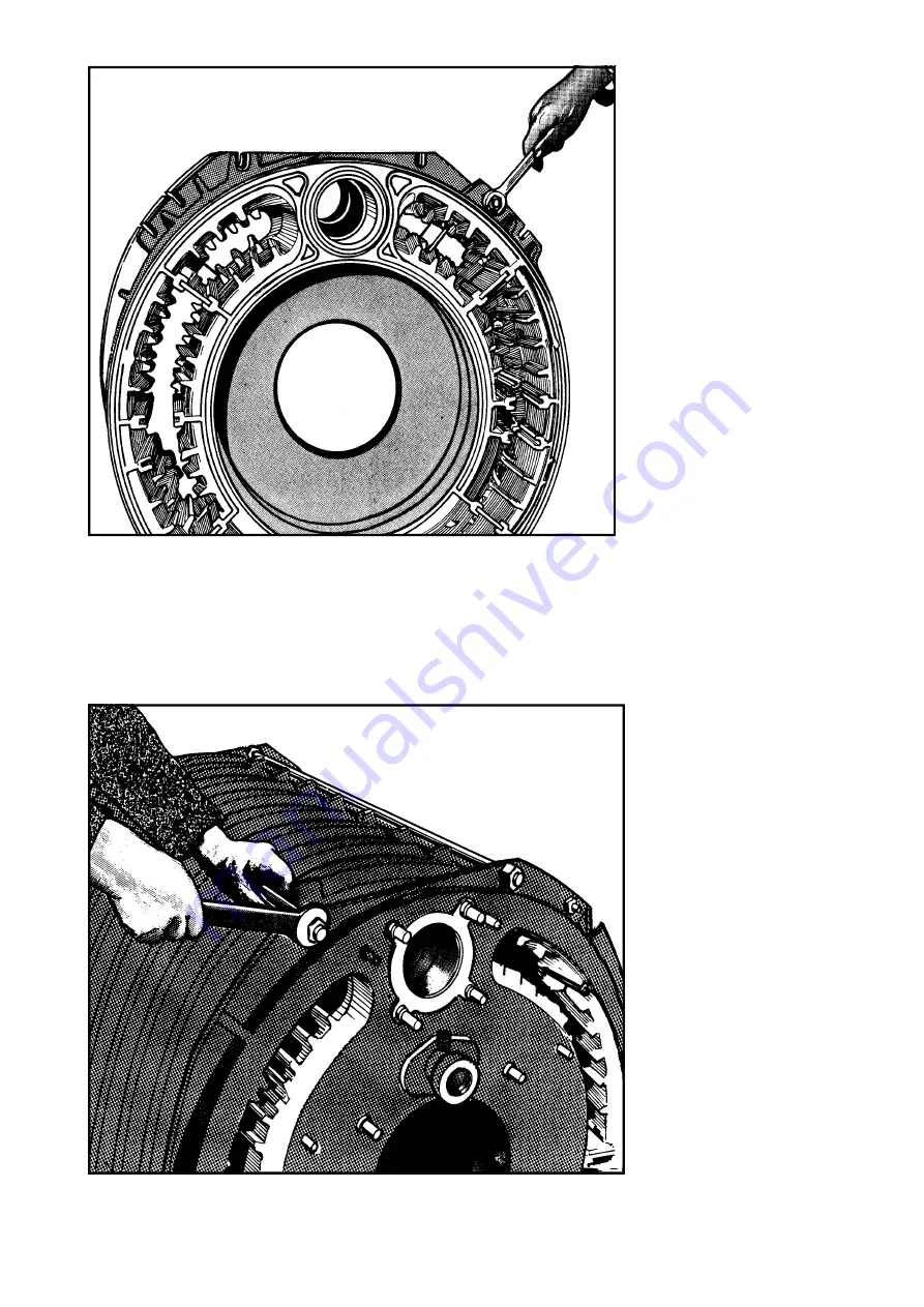
Figure 10.7 – Fitting Lacing Bolts
Figure 10.8 – Fitting Upper Tie Rods
e.
Place the next correct section
(Item 3) onto the cradle and fit to
rear section, carefully locating guide
rings into ports and ensuring that 'O'-
ring seals are correctly located
between the machined faces and are
not pinched or damaged.
f.
Fit one of the lacing bolts (29)
provided through each of the
UPPER RIGHT and LOWER LEFT
pairs of bolt flanges on the sections
(Fig 10.7). Tighten the bolts
EVENLY to a torque of 25Nm (18
lbf.ft.)
N.B.
These bolts are intended only
to keep the sections together during
assembly. To avoid undue stress
during expansion of boiler they
should NOT be overtightened.
g.
Repeat the above procedure
for the remaining sections in the
correct order ensuring that:
* Mastic sealer is fitted into groove
around perimeters of every section
and port.
* Guide rings and 'O'-ring seals
are correctly fitted.
* Lacing bolts are fitted and not
overtightened.
*
Flue plates (19) are correctly
positioned.


