HAMWORTHY HEATING LTD
SHERBORNE
500001103/E
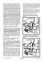
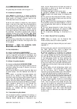
Figure 10.3.3 Connection of Flue System
(Separate Ducts
)
Appliance connector
90° support elbow
Mounting bracket
Flue elbow
Air inlet box
ø80/100 eccentric
ø100 Flue
adapter
10.3.4 Connection of Single Pipe Horizontal/
Vertical Open Flue – 100mm
Note:
the flue support cradle is not required for this
installation and should be discarded.
Refer to Figures 6.1.4 and 10.3.4. Secure the flue
elbow mounting bracket to the wall frame using 3 –
M6 nuts and washers. Locate the 90°-discharge
elbow onto the right hand mounting bracket lug and
fit the appliance connector duct between the flue
outlet in the aluminium boiler casing and the 90°
elbow. The vertical leg of this duct is telescopic to
assist with installation. Locate the air inlet terminal
into the left hand 90° elbow. Fit the remaining flue
components on route to the terminal discharge
ensuring a minimum 2° slope and that the flue
system is self supporting using wall brackets where
necessary. In terminating the flue system, ensure
that the joint through the wall / roof is made good
and weatherproofed. The top of the plastic boiler
cover has a D shaped recess that marks the
position of the vertical flue exit point. Using a
suitable fine toothed hacksaw or jigsaw, carefully cut
around the inside of the recess to provide the flue
outlet.
Having fitted the flue system to the boiler, carefully
refit the burner assembly and secure to the heat
exchanger using the 2 – M6 nuts previously
removed taking care not to damage the probes or
the burner flange gasket see Figure 10.2.
Reconnect the pressure feedback tube to the gas
valve.
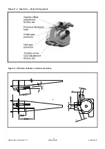
Figure 10.3.4 Connection of Single Pipe (Open Flue)
Air inlet
Flue elbow
90° support elbow
Mounting bracket
Appliance connector
ø80/100 eccentric
adapter
ø100 Flue
Air inlet box
terminal
10.4
Water Connections
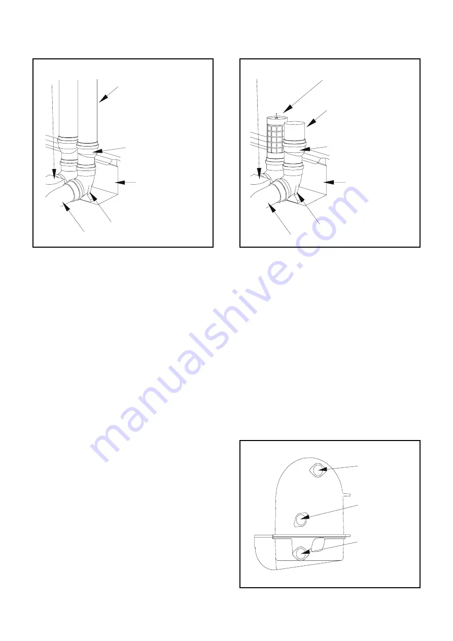
See Figure 10.4. Care must be taken when installing
water system pipework that undue stress is avoided
on the boiler flow and return connections. It is
recommended that unions are fitted local to the
boiler and outside of the casing, to permit future
servicing requirements. Fully closing valves must
not be connected to both flow and return pipes
unless the boiler is fitted with an individual, correctly
sized and positioned safety valve. It is
recommended that a 3-way 'T' port valve is fitted in
the flow connection to allow an open vent situation
should the boiler need to be fully isolated from the
system.
To ensure that the flow and return pipework are
retained within the boiler casing,
it is
recommended that swept bends are not used.
To
achieve this use 1
1/4
” elbows or tees.
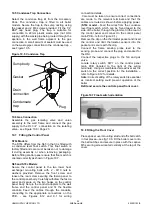
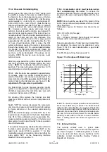
Figure 10.4 Water Connections
Flow
Return
Return
S65 Model
S70c Model
21
Summary of Contents for Sherborne S65
Page 8: ...HAMWORTHY HEATING LTD SHERBORNE 500001103 E Figure 1 1 Boiler Installation Typical 2 ...
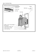
Page 29: ...HAMWORTHY HEATING LTD SHERBORNE 500001103 E Figure 10 6 Gas Pipe Fitting 23 ...
Page 45: ...HAMWORTHY HEATING LTD SHERBORNE 500001103 E NOTES 39 ...
Page 46: ...HAMWORTHY HEATING LTD SHERBORNE 500001103 E NOTES 40 ...
Page 47: ...Notes ...


