HAMWORTHY HEATING LTD
SHERBORNE
500001103/E
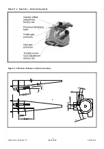
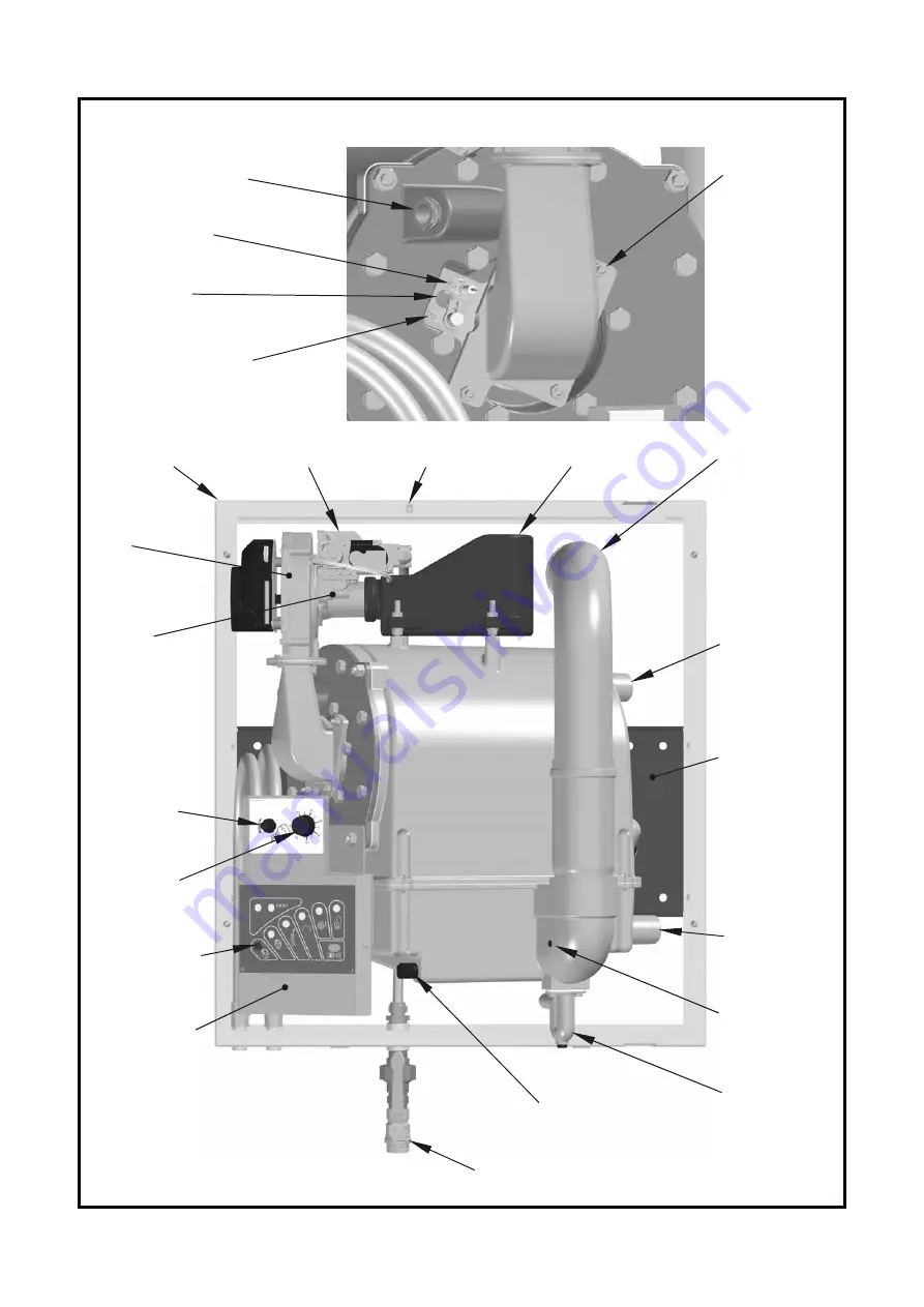
Figure 11.1 Boiler Layout
Water Flow
Connection
Water Return
Connection
†
Wall Plate
Condensate
Drain Trap
Condensate Level
Float Switch*
Gas Supply
Isolating Valve
Control Panel
Lockout Reset
Button
Control
Thermostat
Limit
Thermostat
Fan
Venturi
Gas Valve
Air Inlet Chamber
Flue Outlet
Wall Frame
* Condensing Models Only
Position varies by model,
condensing model depicted
†
Cover Fixing Point
Thermostat Pocket
Flame Probe
View Port
Hot Surface Igniter
Fan/burner
securing nut
Flue gas
sampling
point
25
Summary of Contents for Sherborne S65
Page 8: ...HAMWORTHY HEATING LTD SHERBORNE 500001103 E Figure 1 1 Boiler Installation Typical 2 ...
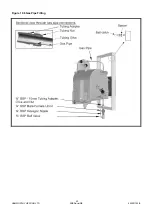
Page 29: ...HAMWORTHY HEATING LTD SHERBORNE 500001103 E Figure 10 6 Gas Pipe Fitting 23 ...
Page 45: ...HAMWORTHY HEATING LTD SHERBORNE 500001103 E NOTES 39 ...
Page 46: ...HAMWORTHY HEATING LTD SHERBORNE 500001103 E NOTES 40 ...
Page 47: ...Notes ...


