background image

 
HAMWORTHY HEATING LTD 

SPETISBURY 


500001118/C 

Where the system is operating on a DT of 20°C, care 
should be taken to ensure that the return temperature 
does not fall below 50°C. 
 

8.9.2  Water Flow Controls 

 
Any external mixing valve/shunt pump or similar 
controls should 

ALWAYS ENSURE

 that the minimum 

water flow rate as shown in Figure 3.1 is maintained. 
 

8.9.3  Frost Protection 

 
Consideration should be given to fitting a frost 
thermostat set at approximately 4°C. 
 

8.10 Unvented Systems 

 
See Figure 15.1 for typical layout of a Unvented 
(Pressurised) Hot Water System. For system design 
refer to 

BS 7074 Part 2. 

 
In order to correctly size a pressurisation unit for any 
heating system certain parameters are required.  These 
are:- 
 

1)

 Static height of highest component in system 

(metres). 

2)

 System volume - if it is not known a general rule of 

thumb of 10 litres/kW of installed boiler power can be 
used.  

3)

 Maximum flow temperature (°C). 

4)

 Maximum system hot working pressure,  generally 

given in bar g. 
 
From the above information Hamworthy Heating can 
size the pressurization unit and also the expansion 
vessel required. Care must be taken in sizing expansion 
vessels to ensure maximum acceptance factors are not 
exceeded.  Normally manufacturers of vessels impose 
a limit of 0.5.  This value must not be exceeded at any 
time during the operation of the boiler: this includes the 
over pressure condition should a safety valve lift. 
 
Consideration should also be given to sizing of the 
safety valve(s) in the system.  See 

BS 6759

:  Part 1, for 

information. See also 

BS 6880

: Part 1 for design 

considerations. 
 

8.11  Modular Boiler Control Schemes 
 

For modular boiler installations, Hamworthy Heating 
can supply a unique boiler management control system 
called the ‘Marshall HE’. This system comprises: a wall 
mounted master control unit, which houses the main 
interface processor and will control up to 8 stages. For 
further information, contact Hamworthy Heating for 
details. 


8.5  Thermometer 

 
See Figure 15.1 for typical position. 
A thermometer complete with pocket should be fitted in 
the pipework to indicate water flow temperature. 
 

8.6  Drain Valves 

 
Each boiler should have ¾” NB drain valve fitted (not 
HHL supply),  to drain the boiler only. A plugged Rc ¾” 
connection is provided for a drain valve at the bottom of 
the front boiler section. The heating system in total 
should have drain valves as recommended by 

BS 

6644

. See Figure 15.1 for recommended positions. 


8.7  Circulating Pump 
 

One or more circulating pumps will be required to 
circulate water around the boilers and heating system. 
The pump should be sited to facilitate servicing. It is also 
important that the existing system be flushed through 
twice to remove any loose matter, which may have 
accumulated.  If in any doubt regarding the cleanliness 
of the system, a coarse filter should be fitted in the 
return pipework to the boilers. 

NOTE: 

If boilers are run off time clock control, a pump 

overrun (not HHL supply) should be fitted which must 
run for a minimum of 5 minutes on shut-down of the last 
boiler. 
 

8.8  Minimum Water Flow Rates 

 
Minimum water flow rates are shown in Figure 3.1. 
These flow rates should be maintained through the 
boiler at all times whilst the boiler is firing. If the 
water flow rate is allowed to fall below the minimum, 
the boiler heat exchanger could fail due to the 
resultant scale formation. Particular attention should 
be paid to the restriction of external flow circuits 
during periods of low heat demand. 

 
8.9 Control Schemes


8.9.1  Temperature Controls 

 
An adjustable control thermostat is supplied with each 
boiler and should be set to operate within the range 65-
90°C for standard applications. A temperature limiter, 
(hand reset limit thermostat) is also fitted to the boiler 
and must be set at 100°C.  

NOTE!

 The minimum difference between control 

thermostat and temperature limiter 

must never

 be less 

than 10°C. 

Boiler Output 

Feed 

Vent 

60kW - 150kW 

25 

32 

150kW – 300kW 

32 

38 

300kW – 600kW 

38 

50 

Figure 8.3. Cold Feed and Vent Pipe Sizes (mm)


Summary of Contents for Spetisbury

Page 1: ...MUST BE READ AND UNDERSTOOD BEFORE INSTALLING COMMISSIONING OPERATING OR SERVICING EQUIPMENT Spetisbury Boilers Gas Fired Cast Iron Sectional Boilers 110kW to 340kW Installation Commissioning and Serv...

Page 2: ...ating safely and efficiently Maintenance Agreements 01202 662555 Regular routine servicing of equipment by Hamworthy service engineers inspects the safety and integrity of the plant reducing the risk...

Page 3: ...ON GROUP H NATURAL GAS 2ND FAMILY I2H PLEASE ENSURE RELEVANT INFORMATION REQUIRED WITHIN DOCUMENT IS FOUND RELATING TO SPECIFIC FUEL TO BE FIRED BEFORE FIRING BOILER THIS BOILER COMPLIES WITH ALL REL...

Page 4: ...aste Gas Volume and Temperature 6 3 Materials 6 4 Suction 6 5 Disconnection 6 6 Flue Discharge 6 7 Surface Temperatures 6 8 Flue System Location 6 9 Condensate Discharge 7 0 AIR SUPPLY 6 7 1 Air Suppl...

Page 5: ...nd Vent Pipe Sizes 7 Figure 9 1 Electrical Wiring Diagram 8 Figure 10 1 Composition of Sections Within Heat Exchanger 9 Figure 10 2 Boiler Section Identification 10 Figure 10 3 Rear Section and Cradle...

Page 6: ...nstallation Typical 30 Figure 15 2 Dimensions and Clearances 31 Figure 15 3 Burner Clearances 31 Figure 15 4 Stacked Boiler Dimension 32 Figure 15 5 Burner Mounting Plates Dimensions SP 110 150 220 33...

Page 7: ...er The section to section flue gas seal is made by d A mastic strip around the outer perimeter of each section e A mastic strip around the perimeter of the combustion chamber of each section The secti...

Page 8: ...box f Burner mounting plate drilled ready to accept burner SP 110 150 220 only Burner mounting plate not required on SP 280 or 340 g Steel cradle Remove all the packing material and inspect the equip...

Page 9: ...uidance note PM5 Automatically controlled steam and hot water boilers CIBSE Publications CIBSE Guide It is impractical in this document to specify all relevant information but the following extracts f...

Page 10: ...weight of the boiler including pipework and ancillary equipment when filled with water A steel sheet can be placed beneath the boiler cradle to facilitate movement of the boiler during assembly If a...

Page 11: ...s not connected to a chimney system but is connected directly to outside by a standard stainless steel flue either single or twin wall it is particularly important to ensure that the point at which it...

Page 12: ...d except by a design which when closed for maintenance the boiler is open to atmosphere The pipe shall be protected against freezing where this might occur 8 4 Altitude Gauge Water Pressure Gauge Ever...

Page 13: ...information contact Hamworthy Heating for details 8 5 Thermometer See Figure 15 1 for typical position A thermometer complete with pocket should be fitted in the pipework to indicate water flow tempe...

Page 14: ...d to the earthing system and never reverse the Live and Neutral connections 9 2 GAS TRAIN INSTALLATION The gas train installation should be carried out by suitably qualified and competent personnel Be...

Page 15: ...made up by inserting the flue plates and locking nuts into position with nuts and bolts The plates MUST be inserted into the sections in the slots provided and the number and position of the plates MU...

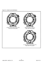
Page 16: ...TISBURY 500001118 C Figure 10 2 Boiler Section Identification A Rear Intermediate section RI Fitted with 4 flue plates C Front Intermediate section FI Fitted with 2 flue plates B Intermediate section...

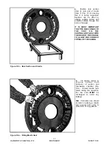
Page 17: ...aps through the ports or flueways IT IS MOST IMPORTANT THAT THE BACK EDGES OF THE FEET ON THE CASTING ARE FLUSH WITH THE REAR OF THE CRADLE TO ALLOW FOR CORRECT FITTING OF THE CASING b Fit sealing mas...

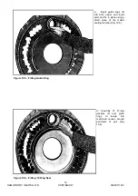
Page 18: ...Figure 10 6 Fitting O Ring Seal c Insert guide rings 6 into both upper and lower ports and fix in place using a small piece of the mastic sealing material Fig 10 5 d Carefully fit O ring gaskets 5 ove...

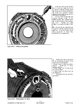
Page 19: ...of the UPPER RIGHT and LOWER LEFT pairs of bolt flanges on the sections Fig 10 7 Tighten the bolts EVENLY to a torque of 25Nm 18 lbf ft N B These bolts are intended only to keep the sections together...

Page 20: ...gure 10 9 Fitting Lower Tie Rods Figure 10 10 Flue Gas Flow Path h After fitting front section 2 fit the four tie rods 30 through the lugs on top and bottom of front and rear sections Figs 10 8 10 9 T...

Page 21: ...board large enough to accept the burner blast tube Note Burner mounting plate NOT required on SP 280 and SP 340 models c Locate the foil covered insulation wrap which comprises a front blanket a rear...

Page 22: ...uts and washers fit front and rear cross members to M6 studs protruding from body of boiler 2 Using M6 nuts and washers fit casing support rails to M6 studs on front and rear cross members Note positi...

Page 23: ...ion 5 Attach casing support strut to front edges of side panels and secure with M5 x 10 pozi screws and washers Note On assemblies with two side panels secure panels together with M8 x 16 hex head scr...

Page 24: ...ashers Note Ensure that rear cover is located in correct position as indicated below 8 After mounting burner on burner mounting plate fit plastic strikers and latches to upper and lower covers and sid...

Page 25: ...burner and the Live and Neutral should be correctly connected c The gas pipe work is of a suitable size for the burner requirements and the installation has been checked for leaks and fully purged On...

Page 26: ...y until the desired level is reached h Replace the gas valve security cover i Manually drive the fan speed back to maximum by pressing the hidden button at the same time as the plus button Once again...

Page 27: ...lating water 4 The pipework and valve arrangement is installed to Hamworthy Heating recommendations in such a way that water flow rates will be in accordance with Figure 3 1 5 The gas supply pipework...

Page 28: ...figures nominated in section 10 6 of this manual IF BURNER REPEATEDLY FAILS TO LIGHT A FULL INVESTIGATION TO FIND CAUSE SHOULD BE MADE h Check gas flow rate at meter Ensure that all other appliances...

Page 29: ...r FLOW NTC1 and RETURN NTC2 temperature sensors have been exchanged Boiler FLOW NTC1 and RETURN NTC2 temperature sensors are not equal in rest position Boiler FLOW NTC1 and RETURN NTC2 temperature sen...

Page 30: ...HAMWORTHY HEATING LTD 24 SPETISBURY 500001118 C Figure 12 2 Fault Finding Flowchart...

Page 31: ...is manual e Examine all gasket material and check for any signs of damage or degrading If necessary replace them but always use the correct type f Check all electrical connections and cables to ensure...

Page 32: ...n procedure In each case the operation of each replaced component must be checked by carrying out the appropriate part of the commissioning procedure See Section 11 0 COMMISSIONING TESTING NOTE Isolat...

Page 33: ...82 Not Required on SP 280 or SP 340 Models 13 Burner Mounting Plate 530805065 Not Required on SP 280 or SP 340 Models 14 Sight Glass Insulation Gasket 573405184 15 Sight Glass Assembly 573405185 16 Ga...

Page 34: ...er Head Gasket 533306069 Fan Gasket 533306070 Burner Head 533306071 Inlet Gas Flange kit 533306072 Gasket Kit 563605284 Service Kit 563605285 Fan Control Control Box Gas Valve Electrodes Burner Head B...

Page 35: ...it 533306076 Gasket Kit 563605284 Service Kit 563605285 Spetisbury SP 280 Control Box 533306079 Gas Valve 533306080 Fan Unit 533306081 Mounting Plate Gasket 533306082 Burner Head Gasket 533306083 Fan...

Page 36: ...HAMWORTHY HEATING LTD 30 SPETISBURY 500001118 C Figure 15 1 Boiler Installation Typical 15 0 TECHNICAL DATA...

Page 37: ...It may not however be adequate for the installation of flue bends within the boiler house Where necessary the dimension must be increased accordingly Figure 15 3 Burner Clearances Boiler Burner Model...

Page 38: ...HAMWORTHY HEATING LTD 32 SPETISBURY 500001118 C STACKED BOILER DIMENSIONS Front View Figure 15 4 Stacked Boiler Dimensions...

Page 39: ...ate is supplied the dimensions of which are shown below Figure 15 5 SP 110 150 220 Burner Mounting Plate Dimensions When installing a Spetisbury SP 280 or SP 340 a burner mounting plate is not require...

Page 40: ...t3 h 6144 8333 10381 13532 16501 GAS DATA NOMINAL GAS INLET PRESSURE mbar 20 MAXIMUM GAS INLET PRESSURE mbar 25 GAS FLOW RATE m3 h 13 3 18 2 26 5 32 8 39 9 ft3 h 469 5 642 5 935 5 1157 1410 GAS INLET...

Page 41: ...SP 150 206 7 45 4 6 5 2 6 108 23 8 1 8 0 7 SP 220 286 7 63 1 11 5 4 5 157 7 34 7 3 7 1 5 SP 280 357 5 78 6 16 5 6 6 196 3 43 2 5 0 2 0 SP 340 435 0 95 7 21 0 8 4 240 0 52 8 6 4 2 6 Figure 3 1 Water F...

Page 42: ...HAMWORTHY HEATING LTD 36 SPETISBURY 500001118 C NOTES...

Page 43: ...Notes...

Page 44: ...y reserves the right to make changes and improvements which may necessitate alteration to the specification without prior notice Connect direct Direct Dial Telephone and Fax Numbers Direct Email Addre...

Reviews: