background image

IMPORTANT NOTE

THESE INSTRUCTIONS MUST BE READ 

AND UNDERSTOOD BEFORE INSTALLING, 

COMMISSIONING, OPERATING OR 

SERVICING EQUIPMENT

INSTALLATION, COMMISSIONING AND

SERVICING INSTRUCTIONS

Hot water preheating with gaz complement

TYNEHAM HEAT PUMP CONTROL

For all Tyneham heat pumps 

Summary of Contents for TYNEHAM AHP60 14/18

Page 1: ...T BE READ AND UNDERSTOOD BEFORE INSTALLING COMMISSIONING OPERATING OR SERVICING EQUIPMENT INSTALLATION COMMISSIONING AND SERVICING INSTRUCTIONS Hot water preheating with gaz complement TYNEHAM HEAT PU...

Page 2: ...fely and efficiently Maintenance Agreements Regular routine servicing of equipment by Hamworthy service engineers inspects the safety and integrity of the plant reducing the risk of failure and improv...

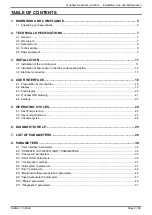
Page 3: ...USER INTERFACE 18 4 1 Presentation of the interface 18 4 2 Display 18 4 3 Fault display 20 4 4 Tyneham HMI browsing 21 4 6 Settings 23 5 OPERATING CYCLES 24 5 1 Heat Pump start up 24 5 2 Heat pump shu...

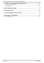
Page 4: ...e and Maintenance 9 HYDRAULIC DIAGRAMS AND CONFIGURATIONS 53 9 1 Symbols used in the diagrams 53 9 2 List of diagrams 54 10 ELECTRICAL VALIDATION 77 12 SPARE PARTS LIST 78 11 LACK OF WATER SAFETY FUNC...

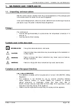
Page 5: ...attention to comments CAUTION Failure to follow these instructions may cause damage to the installation or to other objects WARNING Failure to comply with these instructions may cause injury and serio...

Page 6: ...Wiring Regulations CAUTION Before opening the Tyneham Heat Pump Control regulator unit make sure that no water is present on the top of the case CAUTION The control panel is classified as an appliance...

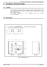
Page 7: ...l panel is used to control the heat pump and the hydraulic station In this way it is possible to produce domestic hot water according to the Tyneham Heat Pump Control operating mode For further inform...

Page 8: ...Pump Control Installation Use and Maintenance figure 2 Dimensions in mm Version with mounting feet 2 3 Delivered unit Case Servicing installation and maintenance instructions Wiring diagram Locking k...

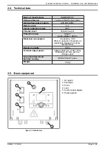
Page 9: ...llution level II Protection index Class I surge voltage 800 V Electrical consumption On standby 10W When in operation Depends on appliances plugged in pumps mixing valves Relative humidity 95 Terminal...

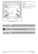
Page 10: ...egulator is protected with a 6 3 A fuse The total load of the consuming elements connected to this regulator must not be more than 6 3 A INFORMATION The electrical connection diagrams temperature sens...

Page 11: ...t Open and remove the door by removing the hinge pins shown in figure 6 from the outside Attach the mounting feet using the four screws supplied in the bag Refit the door by proceeding as for removal...

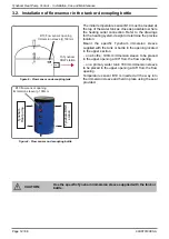
Page 12: ...h the tank or bottle in the opening located in the upper section on a bottle 100mm immersion sleeve to be placed in the upper opening at 90 from the flow opening on a primary water tank 160mm immersio...

Page 13: ...arry out electrical connections in particular connection to the main supply when all other fitting and installation work is completed WARNING Installations carried out by the customer cable runs gas o...

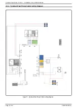
Page 14: ...Page 14 86 00U07310080 A Tyneham Heat Pump Control Installation Use and Maintenance 3 3 2 Tyneham Heat Pump Control wiring diagram figure 11 Tyneham Heat Pump Control wiring diagram On Off...

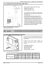
Page 15: ...n of similar qualification to avoid any danger Tow presses must be tightened tightly enough to withstand cable traction up to 60N CAUTION The Tyneham Heat Pump Control must be powered by special prote...

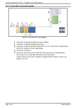
Page 16: ...Connection of W3100 hydraulic station with H1 M R1 NO and Com respectively and H3 M R2 NO and Com respectively G Connection of Rubis E1 H Connection of the HP s alarm summary relay output and the hyd...

Page 17: ...CAUTION Ensure each cable gland is tight so that no connection inside the control panel can be attempted 3 3 6 Changing the Fuse figure 15 Fuse slot Set the switches to Off Switch off the electric pow...

Page 18: ...on of the interface The Tyneham Heat Pump Control controller user interface comprises An On Off switch An Tyneham system fault summary indicator light whether alone or cascaded A back lit LCD display...

Page 19: ...evel parameter settings screen 5 seconds Start up Installer OEM with code 4 2 2 Tyneham HMI preset standard browser display The basic display of the Tyneham Heat Pump Control in DHW pre heating mode i...

Page 20: ...y This type of fault does not cause operation to be blocked requiring manual intervention Once the source of the fault has been removed the bell disappears automatically When a fault causes the heat p...

Page 21: ...t Pump Control Installation Use and Maintenance 4 4 Tyneham HMI browsing Only if fault in progress Only if USB drive detected with suitable files OH2 available only on Tyneham AHP60 50 or 70kW U user...

Page 22: ...P status From the basic display you can scroll basic heat pump information see list below Access Setting Exit ESC 1 HP status 2 DHW status 3 Outdoor temperature 4 DHW temperature 5 Heat pump return te...

Page 23: ...this value using the knob The new value is validated by pressing OK 4 6 2 Commissioning and Specialist level parameter settings From the standard display the Commissioning and Specialist parameter se...

Page 24: ...shutdown cycle is applied Tyneham Heat Pump Control display Tyneham display Pump and compressor running Pump running Standby state Note The system always applied a minimum 5 minute stop time before re...

Page 25: ...ters in the maintenance menu YES 134 YES Heat pump alarm Tyneham fault summaries Check the status and presence of a fault on the Tyneham HMI NO 174 YES Hydraulic station error Note the error code on t...

Page 26: ...ance 7 The heat pump start up counter has reached the limit set for preventive maintenance 8 Compressor start up frequency is too high analyse the malfunction Acknowledgement of this error message is...

Page 27: ...tion ribbon cables and the accessories connected to CL CL G Navipass Modbus Operation button is locked in stand by Cannot select the heating circuit or hot water mode from the front panel buttons Cann...

Page 28: ...930 Sensor input BX1 S 8 5 2 page 40 5932 Sensor input BX3 S 8 5 1 1 page 39 Line No Programming Access See subsection page 5933 Sensor input BX4 S 8 5 1 1 page 39 5950 H1 input function S 8 5 1 1 pag...

Page 29: ...8 11 1 page 52 8127 Generator 14 status 8 11 1 page 52 8128 Generator 15 priority 8 11 1 page 52 8129 Generator 15 status 8 11 1 page 52 8130 Generator 16 priority 8 11 1 page 52 Line No Programming...

Page 30: ...times The time changes automatically at 2 am winter time to 3 am summer time or from 3 am summer time to 2 am winter time on the first Sunday after the respective dates 8 1 2 User interface Line no P...

Page 31: ...t the programming level To do this press the OK and ESC buttons together for at least 3 seconds The programming locking function temporary suspension remains effective until the user quits the program...

Page 32: ...00 563 2nd period start time 00 00 24 00 564 2nd period stop time 00 00 24 00 565 3rd period start time 00 00 24 00 566 3rd period stop time 00 00 24 00 576 Default values No Yes The Tyneham Heat Pum...

Page 33: ...2 00 and 06 00 the next day If no setting is made for 8 minutes the screen returns automatically to the basic display INFORMATION Every time the user accesses the DHW timer programme 4 menu the first...

Page 34: ...s the DHW and DHW tank menus when a sensor is connected to its B3 input The control adjusts the DHW temperature to the desired setpoint according to the timer programme 8 2 1 Basic settings 8 2 1 1 Se...

Page 35: ...The parameters and the diagram below describe the DHW charge regulation Line no Programming Possible values 5008 DHW start of charge delay 0 30 min This parameter allows the heat production provided...

Page 36: ...W setpoint In order to correctly define the starting point for this gradual setpoint the Tyneham generator is released at its minimum modulation and the plate exchanger is released In this way tempera...

Page 37: ...alarm function on each controller INFORMATION The QX4 output must be a summary of installation faults that includes the hydraulic station It is not possible to distinguish between faults from specifi...

Page 38: ...alve Q3 5894 Relay output QX4 Alarm output K10 Alarm output K10 Alarm output K10 Alarm output K10 5932 Sensor input BX3 B10 line output sensor B10 line output sensor B10 line output sensor B10 line ou...

Page 39: ...mption circuit pump 1 Q15 Function not available Alarm output K10 If a fault occurs it is reported by the alarm relay Contact closure has a two minute delay time Once the error is eliminated i e the e...

Page 40: ...ensor 1 Special temp sensor 2 Outdoor sensor B9 Room thermostat B5 Room thermostat B52 Room thermostat B53 The output settings assign the corresponding functions based on the selection None No functio...

Page 41: ...unction is active at input H3 The input causes a regulator error message If the alarm output is configured accordingly relay outputs QX4 line 584 then the error is forwarded or displayed by an additio...

Page 42: ...as the regulator has already been running for at least two hours If a sensor fails after registration then the standard device generates an error message This setting is used to immediately register...

Page 43: ...he system time by the master The regulator time is however automatically and constantly adapted to match system Master The time can be set on the regulator The regulator time becomes the reference tim...

Page 44: ...ogramming Possible values 6700 In progress 00 00 23 59 h m 8 7 2 History Line no Programming Possible values 6800 6802 6804 6806 6808 6810 6812 6814 6816 6818 History 00 00 23 59 h m The unit stores t...

Page 45: ...the period of time in months since the last service check If the value is over the Heat pump interval setting Heat pump maintenance The symbol is displayed and A maintenance message is provided at th...

Page 46: ...mpressor does not come back on automatically if the heat pump reaches a safety limit value during the active commissioning process In this case the output selection is reset 7207 0 but the commissioni...

Page 47: ...lay output QX3 Relay output QX4 Relay output Q5 Relay output QX21 module 1 Relay output QX22 module 1 Relay output QX23 module 1 Relay output QX21 module 2 Relay output QX22 module 2 Relay output QX23...

Page 48: ...1 H2 H3 Line no Programming Possible values 7840 H1 voltage signal 0 10 V 7841 H1 contact status Open Closed 7845 Module 1 H2 voltage signal 0 10 V 7846 Module 1 H2 contact status Open Closed 7848 Mod...

Page 49: ...Load locked 81 Load locking active 82 Forcing maximum temperature of the tank 83 Forcing maximum temperature of load 84 Forcing anti Legionella setpoint 85 Forcing comfort setpoint 86 Forced load act...

Page 50: ...inimum active compr stop time 35 Time limit active 37 Maximum active compr stop time 38 Compressor EN 46 Heating mode 137 Locked max return temperature 261 Locked min return temperature 262 Locked max...

Page 51: ...HW separation activated Out Temp limitation active Not released Released 8138 Cascade starting temperature 0 140 C 8139 Cascade starting setpoint 0 140 C 8140 Cascade return temperature 0 140 C 8150 C...

Page 52: ...temperature 2 B31 0 140 C 8840 Number of DHW pump hours 0 8333 7 00h 8841 DHW pump starts counter 0 199999 8950 Line start temperature 0 140 C 8951 Line start setpoint temperature 0 140 C 9016 Special...

Page 53: ...installation is used the flow must be balanced between all units We recommend performing this balancing using balancing valves so that individual flow levels can be measured over time CAUTION Flow adj...

Page 54: ...bottle or tank 1 DHW pre heating tank Heat Pump only with two Pre Heating Tanks 60 2 or 3 DHW preheating tanks 2 or 3 Heat Pumps Cascade with one Pre Heating Tank 65 1 decoupling bottle or tank 1 DHW...

Page 55: ...y with one Pre Heating Tank 1 decoupling bottle or tank 1 DHW pre heating tank Diagrams HYF110 HYF111 page 1 5 A HYDRAULIC DIAGRAM figure 16 Diagram HYF110 figure 17 Diagram HYF111 B REGULATION ACCESS...

Page 56: ...ble duration Care will be taken to ensure that draw offs are virtually non existent during this time period This was defined during the sizing study If it is deemed necessary to implement anti Legione...

Page 57: ...M Controller terminals H1 M Diagrams HYF110 HYF111 page 3 5 E HYDRAULIC STATION F HYDRAULIC STATION PROGRAMMING Start up the hydraulic station INFORMATION The hydraulic station arrives pre programmed...

Page 58: ...figure the hydraulic station output preset Relay output QX3 5892 DHW pump valve Q3 Configure the alarm output preset Relay output QX4 5830 Alarm output K10 Assign the tank flow sensor preset Sensor in...

Page 59: ...djust the timer programming 1st phase Off 562 06 00 h Adjust the timer programming 2nd phase ON 563 22 00 h Adjust the timer programming 2nd phase Off 564 24 00 h Switch the DHW rate to automatic H HY...

Page 60: ...l be taken to ensure that draw offs are virtually non existent during this time period This was defined during the sizing study If it is deemed necessary to implement anti Legionella cycles on the dow...

Page 61: ...s Hydraulic station Terminal block Heat pump A B Ref Diagrams HYF120 page 2 5 When 2 or more DHW preheating tanks are linked to the HP it is necessary to add an isolation valve at the plate exchanger...

Page 62: ...Controller terminals H1 M Diagrams HYF120 page 3 5 E HYDRAULIC STATION F HYDRAULIC STATION PROGRAMMING Start up the hydraulic station INFORMATION The hydraulic station arrives pre programmed and requi...

Page 63: ...eset Relay output QX4 5830 Alarm output K10 Assign the tank flow sensor preset Sensor input BX3 5932 B10 line output sensor Assign the DHW preheating sensor pre set Sensor BX4 output 5933 DHW source B...

Page 64: ...rogramming 2nd phase Off 564 24 00 h Switch the DHW rate to automatic H HYDRAULIC VALIDATION Switch the power to the Tyneham back on It is necessary to adjust the flow rate of the HPtaking the followi...

Page 65: ...de with one Pre Heating Tank 1 decoupling bottle or tank 1 DHW pre heating tank Diagrams HYF210 page 1 6 A HYDRAULIC DIAGRAMS figure 19 Diagram HYF210 B REGULATION ACCESSORIES REQUIRED Quantity Applia...

Page 66: ...the solution shown does not contain the hydraulic or electrical elements used to perform them If this is to be expected please contact our pre sales department to choose the most suitable solution fo...

Page 67: ...Edition 10 2022 Page 67 86 Tyneham Heat Pump Control Installation Use and Maintenance Diagrams HYF210 page 3 6 Heat Pump No 2 Terminal block Heat pump A B Ref MB DB OCI 345 Controller No 1...

Page 68: ...1 terminals QX3 FX3 Controller No 1 terminals H3 M Controller No 1 terminals H1 M F HYDRAULIC STATION PROGRAMMING Start up the hydraulic station INFORMATION The hydraulic station arrives pre programm...

Page 69: ...t Relay output QX4 5830 Alarm output K10 Assign the tank flow sensor preset Sensor input BX3 5932 B10 line output sensor Assign the DHW preheating sensor preset Sensor BX4 output 5933 DHW source B3 Co...

Page 70: ...ating heat pump Preset 5700 AHP60 14 or 60 18 5 AHP60 26 or 60 32 6 AHP60 50 7 AHP60 70 8 LPB network menu Number of the appliance Appliance address 6600 2 Number of the segment preset Segment address...

Page 71: ...ACCESSORIES REQUIRED Quantity Appliance reference Order No OCI kit 1 per heat pump OCI 345 AA059752 Immersion sleeve sensor kit 2 QAZ 36 AA059261 2 Heat Pumps Cascade with 2 or 3 Pre Heating Tanks 1...

Page 72: ...rtment to choose the most suitable solution for your installation It should also be noted that the gas back up is sized to fulfil all DHW requirements on its own This is an additional safety mechanism...

Page 73: ...Edition 10 2022 Page 73 86 Tyneham Heat Pump Control Installation Use and Maintenance Diagrams HYF220 HYF23a page 3 6 Heat Pump No 2 Terminal block Heat pump A B Ref MB DB OCI 345 Controller No 1...

Page 74: ...1 terminals QX3 FX3 2WV tank Controller No 1 terminals H3 M Controller No 1 terminals H1 M F HYDRAULIC STATION PROGRAMMING Start up the hydraulic station INFORMATION The hydraulic station arrives pre...

Page 75: ...station output preset Relay output QX3 5892 DHW pump valve Q3 Configure the alarm output preset Relay output QX4 5830 Alarm output K10 Assign the tank flow sensor preset Sensor input BX3 5932 B10 line...

Page 76: ...ate to automatic Heat Pump No 2 Line No Value Configuration menu Preset the model of heating heat pump Preset 5700 AHP60 14 or 60 18 5 AHP60 26 or 60 32 6 AHP60 50 7 AHP60 70 8 LPB network menu Number...

Page 77: ...ntrol output Relay test 7700 Output QX3 Cancel enable Relay test 7700 No test Generator diagnostics menu Check the values for the heat pump in use Heat pump flow sensor Heat pump flow temperature 8412...

Page 78: ...t indicator light AA79691 010 Tyneham Heat Pump Control switch cover AA79694 011 Tyneham Heat Pump Control wall mounting AA79690 Tyneham Heat Pump Control x84 x86 connectors AA79698 Complete wiring se...

Page 79: ...Edition 10 2022 Page 79 86 Tyneham Heat Pump Control Installation Use and Maintenance figure 22 Tyneham Heat Pump Control set 001 011 002 007 005 006 008 003 010 009 004...

Page 80: ...d with the control panel to be ordered separately as acces sories 2 QAZ36 immersion sensors CTN 10 k 25 C Ref AA059261 Install the sensor in the sensor immersion sleeve Bulb length 40 5 mm diameter 6...

Page 81: ...1 30 0 827 47 0 451 20 0 7 578 3 0 3 279 14 0 1 555 31 0 796 48 0 436 19 0 7 193 2 0 3 131 15 0 1 492 32 0 767 49 0 421 18 0 6 831 1 0 2 990 16 0 1 433 33 0 740 50 0 407 17 0 6 489 0 0 2 857 17 0 1 37...

Page 82: ...Page 82 86 00U07310080 A Tyneham Heat Pump Control Installation Use and Maintenance...

Page 83: ...yneham communication bus connected to its Controller regulation Yes No Primary hydraulic circuit Hydraulics performed according to the diagram provided in the study Yes No Fluid conveyed Water Water G...

Page 84: ...pliance with HP power cable sections Yes No Check that connections are tight Done Pre operations With the disconnect switch open please open the fuse holders contained in the HP then close the HP s ma...

Page 85: ...Edition 10 2022 Page 85 86 Tyneham Heat Pump Control Installation Use and Maintenance...

Page 86: ...sh engineering excellence from Hamworthy Heating the commercial heating and hot water specialists Scotland Sales Service McDowall Modular Services 2 Penson Road Queenslie Industrial Estate Glasgow G33...

Reviews: