background image

IMPORTANT NOTE

THESE INSTRUCTIONS MUST BE READ 

AND UNDERSTOOD BEFORE INSTALLING, 

COMMISSIONING, OPERATING OR 

SERVICING EQUIPMENT

INSTALLATION, COMMISSIONING AND

SERVICING INSTRUCTIONS

Air/water monobloc

 heat pump

TYNEHAM AHP60

Models: 26 and 32 kW

Summary of Contents for TYNEHAM AHP60

Page 1: ...NSTRUCTIONS MUST BE READ AND UNDERSTOOD BEFORE INSTALLING COMMISSIONING OPERATING OR SERVICING EQUIPMENT INSTALLATION COMMISSIONING AND SERVICING INSTRUCTIONS Air water monobloc heat pump TYNEHAM AHP6...

Page 2: ...s Regular routine servicing of equipment by Hamworthy service engineers inspects the safety and integrity of the plant reducing the risk of failure and improving performance and efficiency Maintenance...

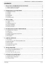
Page 3: ...PRE REQUISITES BEFORE COMMISSIONING 44 4 1 Verification before switching on 44 4 2 Switching On 45 4 3 Commissioning 45 4 4 Adjustment of the heat pump hydraulic flow 45 4 5 Operating diagram 46 4 6...

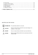
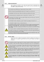
Page 4: ...heck list 65 8 END OF PRODUCT LIFE 71 Symbols used in this document INFORMATION This symbol draws attention to comments CAUTION Failure to comply with these instructions may cause damage to the instal...

Page 5: ...nce with the prevailing regulations and code of practice in particular The legislation on the handling of refrigerants Current I E E BS7671 Wiring Regulations CAUTION This device must be maintained by...

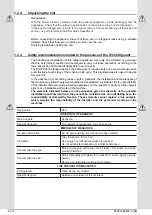
Page 6: ...standards the installation and maintenance of the machine may follow the elements outlined in this standard in particular it is the responsibility of the installer and personnel performing operations...

Page 7: ...ghtly and store in a cool dry well ventilated place Keep in original recipients Incompatible products explosives flammable materials organic peroxide CONTROLLED EXPOSURE INDIVIDUAL PROTECTION Control...

Page 8: ...ion sources such as naked flames electric heaters etc any special work or repairs to the appliance must be carried out by specialised technicians or qualified personnel R32 refrigerant load The proced...

Page 9: ...ation where a refrigerant release may stagnate for example below ground level the installation must meet the requirements relative to gas detection and machine room ventilation 1 2 4 Recommendations f...

Page 10: ...acteristics of the electrical power supply The electrical installation must be conducted in accordance with the regulations in effect and in particular to current I E E BS7671 Wiring Regulations The e...

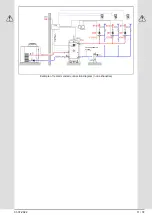
Page 11: ...01 07 2022 11 74 Example of recommended connection diagram non exhaustive TO THE EXPANSION SYSTEM COMMAND TO ELECT CABINET...

Page 12: ...technician must receive the appropriate training and instruction for their tasks in safe conditions Operators should be familiar with personal protective equipment and accident prevention rules prescr...

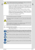
Page 13: ...see Refrigerant Material Safety Data Sheet You should know that refrigerants may not develop an odor For any intervention on the heat pump system Wear appropriate PPE especially gloves and goggles En...

Page 14: ...14 74 00U07362400 A_EN AHP60 26 32 kW Installation Use and Maintenance...

Page 15: ...n relation to the values communicated in chapter 2 4 1 2 3 Definitions Change to monobloc heat pump to be installed outdoors only for heating and or domestic hot water application air water The outdoo...

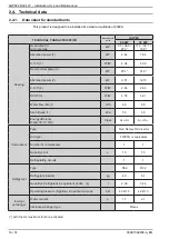
Page 16: ...ergy efficiency Water 35 C 55 C Class A A A A Compressor Type Twin Rotary DC Inverter Oil type FW65S or equivalent Number of compressors 1 1 Quantity of oil L 1 5 1 5 Refrigerating circuits 1 1 Refrig...

Page 17: ...2 Weight for shipping kg 250 265 Weight in service kg 240 255 The above performances are given for the following operating conditions as per the standard 14511 2018 1 Heating external air temperature...

Page 18: ...813 2013 dry temperature humid temperature of the external air 7 C 6 C in out water temperature 47 55 C The tolerance on the value of the total acoustic power level is 2 dB A The value is determined i...

Page 19: ...the outside air 7 C 6 C water temperature inlet outlet 47 55 C The tolerance on the value of the total sound power level is of 2dB A Value is determined according to EN 12102 1 2017 used in conjuncti...

Page 20: ...ure 1 Frame sizes in mm for both 26kW and 32kW Front view Right hand side view Rear view Top view IN OUT 1 M G IN OUT 1 1 4 M G E electricity supply input Dimensions and weight Models 26 kW 32 kW A Le...

Page 21: ...by loosening the screws as indicated in figure 2 3 To access the user terminal unit remove panel B by loosening the screws as indicated in figure 2 4 Insert the cables into the grommets at the rear of...

Page 22: ...with low water flow rates there may be anomalies in how the appliance operates or in the most critical cases the safety mechanisms may intervene Both outdoors and indoors if not insulated heated the...

Page 23: ...el as well as the disconnection and re engagement flow rates for the flow rate controller Water flow rate on the condenser The nominal water flow rate is determined for a temperature difference of 5 C...

Page 24: ...and damage the unit 3 Make sure that the unit remains horizontal while it is being moved 4 Before moving the unit check that the devices are suitable for lifting and preserving the integrity of the un...

Page 25: ...al waste in livestock farms or gas emissions from agricultural machinery A few elements to watch for are also shown in Table on page 27 Determining which corrosive elements are present in the environm...

Page 26: ...appliance does not disturb neighbours or users noise level draughts caused low temperature of the air blown causing a risk of freezing plants in its path Exterior installation on a roof or in an open...

Page 27: ...acturers Oxides Nitrogen oxides NOX x x x Sulphur oxides SxOy x x Carbon oxides x x Volatile gases or liquids Sulphurs x x x Hydrogen fluoride x x Ozone x x Nitrous oxide Methane x Volatile Organic Co...

Page 28: ...reduce the risks it is advisable to study the vibration transmissions from the machine to the building as well as piping reverberation 3 3 2 1 Principle of reflection of the noise emitted Inner court...

Page 29: ...0mm Model A1 mm A2 mm B1 mm B2 mm AHP60 26 kW 400 700 1500 400 AHP60 32 kW 400 700 1500 400 Figure 7 Minimum installation clearances around the outdoor unit CAUTION Do not clog or cover the ventilatio...

Page 30: ...elter or an alcove causes the unit s performances to drop To limit this drop an alcove must have 2 open opposite faces in the axis of the fan If for positioning reasons the open sides cannot follow th...

Page 31: ...e on the base of the hydronic kit on the battery side for the drainage of any condensation that may penetrate through the pipes of the hydraulic system As these pipes are well insulated the production...

Page 32: ...The positions laid down for the installation of the vibration shock absorbers for each type of heat pump are presented in the image below Models Despatch weight kg In service weight kg A mm B mm Xa m...

Page 33: ...ons where the water is hard the use of a water softener does not imply any change in our Guarantee provided that the softener is adjusted in line with trade standards The water hardness must be greate...

Page 34: ...cation Refer to the TYNEHAM Heat Pump Control manual unit control and the design study It is imperative to install adjustment valves not supplied refer to the diagram library In the case of a cascade...

Page 35: ...ess of the water added does not exceed TH 5 f The amount of fill water plus the amount of make up water added during the life of the unit should not be more than three times the water capacity of the...

Page 36: ...eter is vital for a long lifetime for the unit If any of these three above parameters deviates from the above recommendations refer to a water treatment specialist to correct the problem Setting up a...

Page 37: ...fitted on the loading reintegration line The water in the supply filling line must be filtered properly beforehand to remove all impurities and suspended particles Ensure that a removable screen filt...

Page 38: ...mode Screen in OFF mode The circulator is activated for 5 minutes then switches off You can exit the system drain cycle manually To deactivate drain mode PRG MODE ESC PRG PRG OFF PSS 195 PSS OFF SF 1...

Page 39: ...nt cable ducts The flow rate controller item B on the above hydraulic diagram that is factory fitted must ALWAYS be connected in compliance with the indications shown on the electrical wiring diagram...

Page 40: ...ith the inverters we recommend fitting a type B differential circuit breaker as fitting a different type of circuit breaker could lead to unwanted tripping The following table shows the recommended ca...

Page 41: ...01 07 2022 41 74 AHP60 26 32 kW Installation Use and Maintenance...

Page 42: ...aph 2 5 2 The terminal block must be connected in compliance with the remarks below L1 L2 L3 N PE General power supply F1 3 x fuse 32A 10 3 x 38 K1 phase controller Figure 13 Power terminal block 26 3...

Page 43: ...ured in the factory set H84 21 Inverter contact single phase voltage 230Vac 50Hz 5A resistive 1A inductive XP 8 1 8 2 Heat pump fault programmable output CAUTION not configured in the factory set H84...

Page 44: ...appliance s rating plate Ensure that the voltage is definitive and within the tolerance limits 5 Before switching on check if all of the cover panels have been fitted and attached with the appropriate...

Page 45: ...heating is required before the planned commissioning date back up generators may be used TYNEHAM heating system only via the tank back up resistors TYNEHAM hot water system via the gas boiler and the...

Page 46: ...46 74 00U07362400 A_EN AHP60 26 32 kW Installation Use and Maintenance Figure 15 Operating diagram 4 5 Operating diagram 4 5 1 26 32 kW...

Page 47: ...nsor LR Fluid bottle TE SD 1 Temperature sensor on suction line F Filter TE DT 1 Compressor outlet temperature sensor SV Pressure socket PSH 1 HP pressure switch automatic reset HC 1 Housing resistor...

Page 48: ...au sortie t3 T aspir compres t4 T refoul compres t6 non utilis t7 non utilis t9 Pression basse t10 Pression haute t11 non utilis OH1 Heures compres OHP Heures pompe Only if fault in progress Only if U...

Page 49: ...LED ON LED if the compressor is active OFF if the compressor is switched off FLASHING if timer is counting down to start the compressor Not used in this application Frost free resistor LED ON LED if...

Page 50: ...Only if a USB stick is present see software instructions Firmware version Fir Installer Error history Hist Installer Only if there is data in the history Access the PSS menu to enter the maintenance t...

Page 51: ...s are lost and the password needs to be entered once again 5 4 Error menu Err This menu is only displayed if there are errors in progress It allows all of the ongoing errors to be viewed If this is a...

Page 52: ...odes and diagnostic assistance When the heat pump is at fault it displays OFF and the alarm light is on To see the error code you must use PRG2 twice If an automatic reset fault appears the heat pump...

Page 53: ...nto the well and that there is heat dissipating paste Check the refrigerant level E020 Inverter or pressure sensor alarm If the compressors has been operating for more than 150 seconds if the low pres...

Page 54: ...sensor is securely attached to the terminals XC 8 1 XC 8 2 E641 Failure of the compressor discharge sensor intervention of the manual reset pressure switch closed 42 8bar open 34bar The DT1 sensor is...

Page 55: ...the LP1 sensor is attached correctly to the terminals XC 17 1 XC 17 2 E701 High pressure sensor failure The HP1 high pressure sensor is defective Check that the HP1 sensor is attached correctly to th...

Page 56: ...nd the fan board to determine if the opto coupler is working If the LEDs of the compressor inverter board INV1 are not flashing and the board is powered the board INV1 needs to be changed 6 3 Inverter...

Page 57: ...supply voltage variations are too high Check supply voltage Temporary current cut occurred Supply terminals are screws are weak Check the terminals connections strength PFC converter failure Check pr...

Page 58: ...lution E961 Abnormal condition reduce frequency for stop Driver output current or housing temperature exceeded the protection limits The rotor may be stopped since a long time Reduce compressor load R...

Page 59: ...cases we recommend filling the system using an external tap that has been fitted by the installer 7 2 Filling the outdoor unit with water Refer to paragraph 3 6 3 7 3 Prolonged shutdown The methods f...

Page 60: ...be where it is necessary to desolder the pipes we strongly recommend cutting the pipes and not desoldering them with a torch as the flame may trigger the combustion of any oil present It is forbidden...

Page 61: ...rs on the hydraulic circuit X Clean the finned battery with compressed air X Check if the electrical terminals inside the electrical cabinet and on the compressor terminals are attached correctly X Ti...

Page 62: ...leaning treatment every three months Wash preferably with hot water 40 60 C and a pH neutral detergent then rinse thoroughly with cold water 50 L m If the maintenance personnel notices that the protec...

Page 63: ...y qualified technical personnel Place the appliance in a suitable place where there is no risk of leakage of flammable gas Make the installation area inaccessible to third parties Presence of dust wat...

Page 64: ...ay increase weight Consult the table be fore the maintenance phase or refer to the component label in question and choose the most suitable equipment posture for the work to be performed taking into a...

Page 65: ...Sources of ignition When working on a refrigeration circuit containing or having contained flammable refrigerant it is forbidden to use ignition sources that could cause the refrigerant to ignite Remo...

Page 66: ...substances that may cause corrosion Exception refrigerant lines must be made of corrosion resistant materials or be sufficiently protected against corrosion 7 Checking the electrical components The f...

Page 67: ...components suitable for use in flammable atmospheres While we cannot completely rule out exceeding the permissible voltages and currents permanent capacitive or inductive loads must not be connected...

Page 68: ...circuit for repair or other reasons it should be done according to standard procedures In general special care must be taken with regard to the flammability of the refrigerant The following procedure...

Page 69: ...rain equipment We recommend that first of all the refrigerant is recovered Before draining take samples of the oil and refrigerant if the refrigerant needs to be treated The important factor is that t...

Page 70: ...les must contain a safety valve and shut off valves that are firmly attached and in good condition Empty recycling bottles are evacuated and must be cooled down before the suction process if possible...

Page 71: ...ol above must not be put with domestic waste and must be collected separately When the appliance has reached the end of its life cycle and needs to be replaced a number of recommendations must be foll...

Page 72: ...ersons with appropriate technical training obtained through courses recognised by the competent authorities The same precautions described in the previous paragraphs must be followed Special attention...

Page 73: ...01 07 2022 73 74 AHP60 26 32 kW Installation Use and Maintenance...

Page 74: ...rvices 14 46 Lomond Street Glasgow Scotland G22 6JD tel 0141 336 8795 fax 0141 336 8954 Customer Service Centre Hamworthy Heating Limited Wessex House New Fields Business Park Stinford Road Poole Dors...

Reviews: