


01-07-2022
43 / 74
AHP60 26/32 kW -
Installation, Use and Maintenance
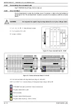
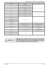
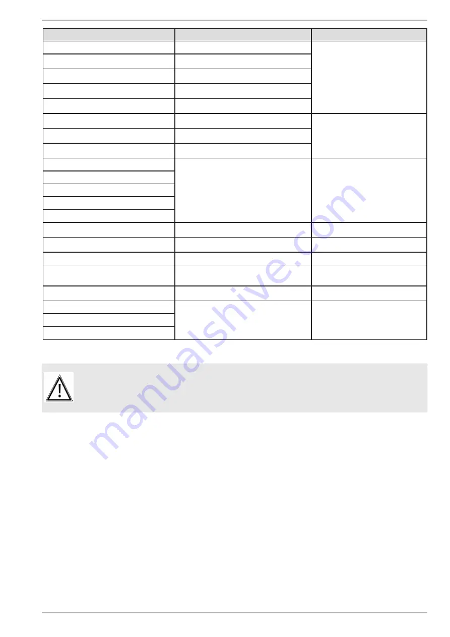
Terminal
Connection
Type
PE
Connect the earth cable
Power supply input 3-Ph/N/PE, 400 Vac, 50Hz
N
Connect the neutral cable from the main power
supply
L1
Connect the L1 phase cable from the main power
supply
L2
Connect the L2 phase cable from the main power
supply
L3
Connect the L3 phase cable from the main power
supply
XC-2.2
Connection TYNEHAM heat pump controller OCI 351
(A+)
Communication bus
XC-2.1
Connection TYNEHAM heat pump controller OCI 351
(B-)
XC-1.1
Connection TYNEHAM heat pump controller OCI 351
(GND)
X12-1
Not used
-
X12-2
XC-12.1/12.2
XC-13.1/13.2
XC-14.1/14.2
XP-7.1/7.2
De-icing signal output (CAUTION: not configured in
the factory, set H84=21)
Inverter contact, single phase voltage 230Vac,
50Hz, 5A resistive, 1A inductive.
XP-8.1/8.2
Heat pump fault programmable output (CAUTION: not
configured in the factory, set H84=47)
Inverter contact, single phase voltage 230Vac,
50Hz, 5A resistive, 1A inductive.
XP-4.1/4.2
Not used
Not used
XC-4.1/4.2
Programmable input (caution, not configured in the
factory, for silent ventilation function set H46=25)
Dry contact
Closed = silence mode activated, Open =
silence mode deactivated
XC-3.1/3.2
Remote on/off input
Dry contact
closed=machine on / open=machine off
XC-19.1
Not used
-
XC-19.2
XC-20.2
IMPORTANT:
If the heat pump is installed in cascade, each unit has its own dedicated
TYNEHAM heat pump controller. The connection between a heat pump and
its control unit must be via a dedicated communication cable. Do not connect
the buses of the different units and control units together.


