HAMWORTHY HEATING LTD
44
UPTON FLOOR STANDING SERIES
500001340/C
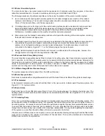
Figure D1 Mechanical Ventilation Flow Rates
Flow rate per kW
total rated heat input (Net)
Inlet air
(Combustion
ventilation)
Difference between
Inlet & Extract air *
m³/h.
m³/h.
Volume
2.6
1.35
APPENDIX E
-
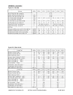
WATER DATA
Note * : Where the associated air extraction is also by means of a fan, this shall be selected such as not to cause
a negative pressure to develop in the boiler house and to maintain the difference between inlet and extract flow
rates shown above.
The calculated extract flow rate is the actual inlet flow rate minus the appropriate figure in the table above.
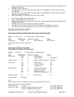
MODEL
UF100
-
1
UF150
-
1
UF200
-
1
UF250
-
1
UF300
-
1
UF350
-
1
Water connections (Flow & Return)
BSP
R2”
Maximum Water Pressure PMW
Bar g
6.0
Maximum Operating Pressure
Bar g
5.3
Minimum Operating Pressure (not including pipe kit)
Bar g
0.5
Minimum Operating Pressure with pipe kit
Bar g
1.0
1.2
1.5
Water content (not including pipe kit)
l
9.0
12.6
16.2
19.8
23.4
27.0
Design Flow Rate @ 20°C
Δ
T Rise
l/s
1.2
1.8
2.4
3.0
3.6
4.2
Waterside Pressure Loss @ 20°C
Δ
T Rise
m/bar
225
250
217
234
246
255
Flow Temperature Set Point (default setting)
°C
80°C
Maximum flow temperature setting
°C
85°C
Minimum flow temperature setting
°C
30°C
Figure E1
-
Water Data
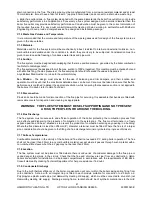
High and low level ventilation grilles shall be positioned as high and as low as practicably possible. Low level
grilles should be located within 1 metre of the floor for Natural Gas and within 250mm of the floor for LPG. High
level grilles should be positioned within 15% of the boiler room height from the ceiling. High and low level grilles
shall communicate with the same room or space where compartment ventilation is used. Where grilles
communicate directly with outside air, they shall be positioned on the same wall.
UF100
UF150
UF200
UF250
UF300
UF350
0
50
100
150
200
250
300
0
0.6
1.2
1.8
2.4
3
3.6
4.2
4.8
P
re
ss
u
re
Dr
o
p
m
/b
a
r
Flow Rate l/s
Hydraulic Resistance - Upton
Figure E1.1 Hydraulic Resistance

