HAMWORTHY HEATING LTD
15
Wessex ModuMax
mk3
Boilers
500001308/C
5.0 BOILER ASSEMBLY
General
Boilers are despatched to site as fully assembled units. The flue collector box (stacked models only) and pipework
manifold set (where applicable) are the only items that will need assembling on site.
Where access is a problem, stacked models can be broken down into individual modules and then re
-
assembled in
the appropriate location in the plant room
-
see section 5.1
During dismantling and assembly it is important to take care to prevent damage to the boiler casing.
Boiler positioning must allow the minimum clearances detailed in Section 3.0 to facilitate access for flue and
pipework connections as well as maintenance.
5.2 Boiler Assembly
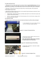
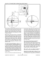
5.2.1 With the boiler in its desired location, loosely
engage the flue collector ducts into each other and
position such that the spigots will fit into the
respective flue sockets at the rear of the boiler.
In assembling the flue ducts, it is advisable to
lubricate the seal located in the socket fittings to
enable easy movement and adjustment.
5.2.2 Fit and secure the bottom closing plate to the
base of the duct assembly.
Do not fit the flue collector at this stage as it may
restrict access to the other connections.
Note:
Should modules be arranged in banks of 2 or
3 high, adjacent to each other, it is advisable to fit
the water and flue connections to each individual
bank prior to fitting the connections to the adjacent
bank(s).
Figure 5.2
-
Flue Collector Box Assembly
Modular Tee
Closing plate with condense discharge
5.1
-
Site dis
-
assembly
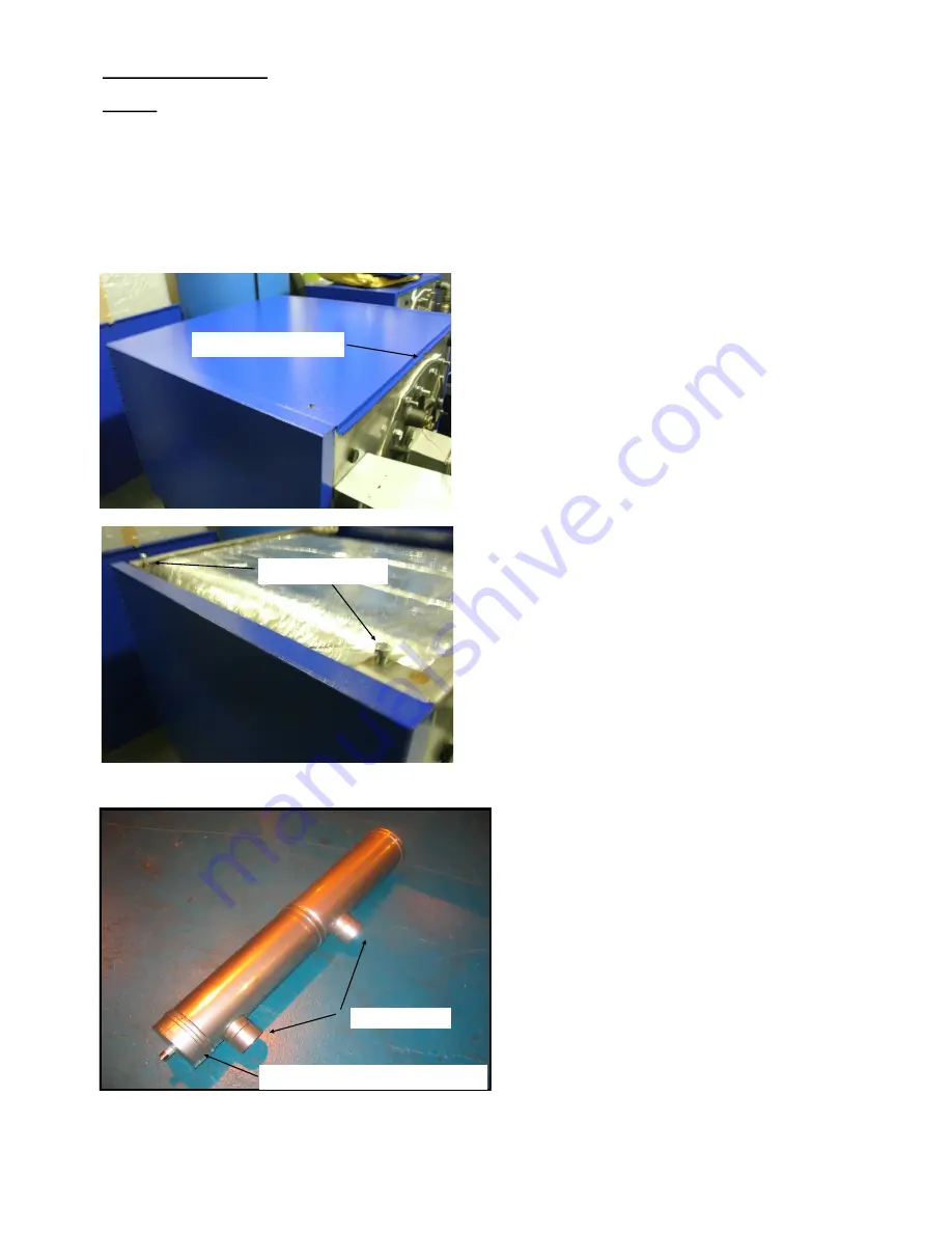
The individual modules are secured by 4 x M8 bolts
securing the boiler frames together
-
see figures
5.1
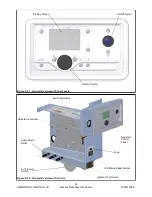
5.1.1 To access the M8 bolts, remove the M8
socket head screw securing the top module front
cover and carefully lift the cover up, disengaging the
locating bracket while lifting off the cover. Carefully
place the cover aside for re
-
assembly.
5.1.2 Remove the pozi screw securing the top
panel to the boiler frame and remove the top panel,
placing aside for re
-
assembly.
5.1.3 Carefully disengage both casing side panels
from the M6 ballstuds.
5.1.4 Access the 4
-
M8 bolts (2 per side) and
withdraw the bolts from the frame. The top module
is now free to carefully lift off the lower module.
Warning
-
the top module is heavy and will require
the appropriate use of lifting methods & equipment
(155kg 97
-
116 models & 200kg 147
-
254 models).
5.1.5 4 x M8 lifting eyes must be placed in the M8
holes in the top of the boiler frame to provide lifting
points.
5.1.6 With the base module in the appropriate
position, carefully rebuild the stacked modules,
securing with the M8 bolts and refit the side panels,
top cover and front cover.
M8 Bolt
-
2 per side
Top panel fixing screw
Figure 5.1 Module fixings


