HAMWORTHY HEATING LTD
25
Wessex ModuMax
mk3
Boilers
500001308/C
8.4 Ignition Controller Check.
1. With the burner firing, the flame signal should be at least 3µA. Refer to
separate Navistem manual
,
,
HHL part
no. 500001310.
To check for correct operation of the ignition controller, close the gas valve. The boiler should
shutdown after approximately one second and attempt a re
-
ignition. Check that the flame has been extinguished
2. Alternatively, the flame probe lead can be removed from the end of the flame probe, with the same result.
8.5 Gas Supply Pressure Check.
1. When the boiler modules have been checked for correct operation the gas supply pressure should be checked.
This should be done with all modules firing.
•
For Natural Gas, a nominal gas inlet pressure of 20mbar measured at the rear of the boiler is required, with
a maximum inlet pressure of 25mbar.
•
For LPG, a nominal gas inlet pressure of 37mbar measured at the rear of the boiler is required, with a
maximum inlet pressure of 45mbar.
8.6 Combustion Checks
“The boiler modules are factory pre
-
set, but site checks must be done to confirm correct performance.”
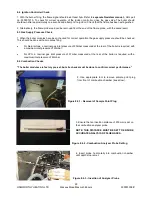
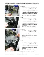
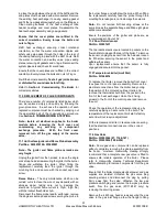
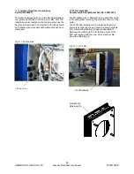
2. Use appropriate tool to remove sample point plug
from front of combustion chamber (see arrow).
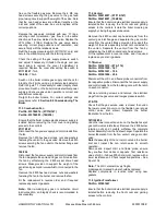
3. Ensure that an insertion distance of 200mm is set on
the combustion analyser probe.
NOTE: THIS DISTANCE MUST BE SET TO ENSURE
ACCURATE ANALYSIS OF FLUE GASES.
Figure 8.6.1
-
Removal of Sample Point Plug
Figure 8.6.2
-
Combustion Analyser Probe Setting
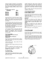
4. Insert probe horizontally into combustion chamber
until depth stop is met.
Figure 8.6.3
-
Insertion of Analyser Probe


