HAMWORTHY HEATING LTD
32
Wessex ModuMax
mk3
Boilers
500001308/C
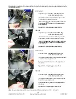
free on the flexible gas pipe. Remove the 4 M5 cap
head screws securing the gas valve to the gas feed
pipe, taking care to support the weight of the valve. Note
that the cap head screws are different lengths at the
inlet and outlet of the valve, be sure to replace at the
correct positions.
Replace the gas valve complete with new ‘O’ rings,
ensuring correct orientation
-
gas flow is in the same
direction as the arrow marked on the valve. Replace the
LPG orifice, if fitted. Replace the gas valve leads,
ensuring correct plug positions and orientation, and
secure firmly with the retained screws.
Refit the low gas pressure switch (97/116/147 only) and
secure the electrical plug with the retaining screw.
Check the setting of the gas supply pressure switch,
and adjust if necessary. Unfasten the single pozi pan
head screw to remove the cover if adjustment is
required. Replace the cover after setting the switch to
97/116/147
-
7mb
196/254
-
7.5mb
Switch on the boiler module gas supply and check for
integrity of all joints using a proprietary leak detector.
Refer to Figure 7.1 if necessary for valve integrity check
procedure. Switch on the boiler module electrical power
supply and ensure gas valve operation is correct and
safe before continuing.
Re
-
light the boiler module. For correct settings and
procedures refer to
Section
8.0
Commissioning The
Boiler
.
11.5 Combustion Fan
Part No. 533704014
-
(97/116/147)
Part No. 533704003
-
(196/254)
Ensure that the boiler module electrical power supply is
isolated before removing the front cover and gaining
access to the controls.
97/116/147
Disconnect the fan power supply and control leads from
the fan.
Remove the 3 M6 hex head screws, nuts and washers
fastening the venturi to the gas valve. Remove the 4 M5
screws securing the fan outlet to the burner flange and
remove the fan.
196/254
Disconnect the fan power supply and control leads from
the fan. Separate the venturi and gas control valve from
the fan by unfastening the 6 M8 socket dome head
screws. Make provision to support the weight of the
venturi and gas control valve whilst not connected to the
fan.
Remove the 4 M8 hex head screws, nuts and washers
fastening the fan to the burner and remove the fan.
Fit the replacement in reverse order, and if required
replace any seals or gaskets.
Note:
-
After re
-
making any gas or combustion circuit
joint/connection, an integrity check is recommended to
ensure safety.
11.6 Venturi
Part No. 532418007
-
(97/116/147)
Part No. 532418001
-
(196/254)
Ensure that the boiler module electrical power supply is
isolated before removing the front cover and gaining
access to the controls. Isolate the boiler module gas
supply by closing the gas service valve.
Remove the 4 M5 socket cap head screws from the
venturi gas inlet flange and separate the gas control
valve from the venturi. Make provision to support the
weight of the valve assembly whilst not connected to
the venturi. Separate the venturi from the fan by
unfastening the 6 M8 socket dome head screws.
Fit the replacement in reverse order, and if required
replace any seals or gaskets.
11.7 Burner
Part No. 533301019
-
(97 & 116)
Part No. 533301020
-
147
Part No. 533301021
-
196
Part No. 533301024
-
254
Disconnect the H.S.I. and flame probe connectors from
the respective probes. Disconnect the fan power supply
and control leads from the fan taking care with the latch
on each connector.
Unscrew retaining screws and remove the electrical
plugs from the gas valve and low gas pressure switch.
97 & 116
Check that the gas service valve is closed, then undo
the lower connection union on the flexible hose (at gas
control valve inlet elbow). Separate the burner
fabrication from the fan .
147/196/254
Undo the lower connection union on the flexible hose (at
gas control valve inlet elbow). Remove the 2 M8 burner
retaining nuts and carefully withdraw the complete
burner assembly from the heat exchanger. Separate the
burner fabrication from the fan, venturi and gas control
valve.
Note
the assembly of the non return valve in the burner
inlet duct. Inspect the non return valve for smooth
operation.
Remove and inspect H.S.I. and flame probe, ensure
they are free from debris or deposits. Test resistance
value of H.S.I. if above 200 ohms (cold), replace with a
lower resistance unit. Check respective positions – See
Figure 13.2.
Note:
-
The H.S.I. element is very fragile.
A damaged or cracked burner should be replaced.
Replace components in reverse order using new
gaskets.
11.8 Ignition Transformer
Part No. 533901441
Ensure that the boiler module electrical power supply is
isolated before removing the front cover and gaining
access to the controls.


