HAMWORTHY HEATING LTD
15
WEYMOUTH
500001112/C
10.3 Advanced Pump Removal (
part n° 530805045 )
1) Isolate water by turning screw in ball valve see fig 21 bellow.
2)
Disconnect the last grey elbow fitting using the blue tool provided. Take care to line up the tool correctly
before pushing the tool into the fitting to release the pipe (see fig 22).
3)
The pressure switch assembly can be pulled forwards (pivots on left corners see fig 23)
4)
Disconnect the outlet pipe from the pump. Remove the quick release clip first (see fig 24)
5)
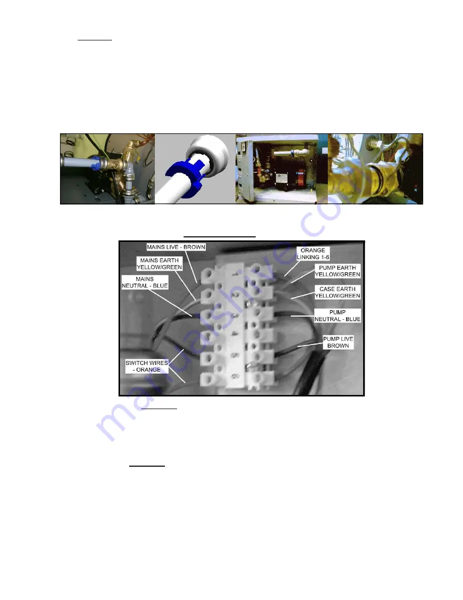
Disconnect the wiring on the mains terminal (see fig 25)
6)
The pump assembly including the mounting plate can now be removed from the unit.
7)
When the pump assembly has been removed the pump can easily be removed from the assembly.
Figure 21
Figure 22
Figure 23 Figure 24
The power lead from the pump is connected to the mains terminal on the back wall of the unit. The connections
are shown in Figure 25 below.
Figure 25 Weymouth Advanced Pump Wiring Terminal
10.3.1 Pump Fitting On Both Units
Pump fitting for each unit is basically the reverse of pump removal.
Care should be taken not to over tighten the 2 pump mounting screws on the Standard units as this can shear
the welded thread. Once re-fitted and connected the pump needs to be bled. Instructions of this can be found in
section 7.6
.
10.4 Inlet Valve On Both Units
(part n°s 531911037 Standard & 531911038 Advanced)
The inlet valve and float in the header tank are supplied as one assembly (see fig 14a and 14b).
The removal/replacement procedure is the same for both units.
1)
Isolate the unit from the water supply.
2) Undo 1/2”BSP connection to remove supply pipe.
3) Unscrew the lock nut from the inlet tube. The valve and float are now free to be removed.
4)
On the standard unit there is a black spacer which fits between the tank and the chassis. This must be
refitted when a new assembly is installed.
5) Once fitted the float adjustment should be set to the lowest level (se section 7.5)


