User Manual RCx-B-xxxAx-8.09
Page 2 of 18
www.hanbayinc.com | 1 800 315 4461
Rev.2021.8 hanbaysales@hanbayinc.com
INSTALLATION
Mounting
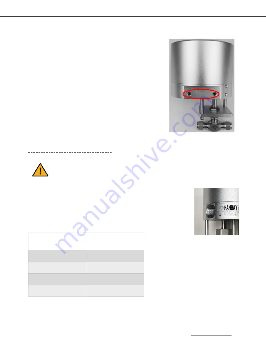
The holes indicated in the image are intended for a mounting
bracket. They are threaded for ¼-
20 and are 0.4” deep.
The other two visible holes are threaded 10-
32, 0.50” deep, and are
intended to be used to lock the lid in position with screws.
For detailed dimensions see p.13.
Wiring
Wiring for Explosion Proof Actuators
The
RCx-AC-B-BxxAx
Explosion-Proof actuator does
not
come with a pre-installed cable, nor
cable gland. A cable gland that meets site specifications for the appropriate hazardous location
rating is required for installation. The cable gland and the cable for hazardous location should
be installed by qualified personnel in accordance with site and local requirements.
The actuator comes standard with a ½” FNPT thread cable entry. See p.14 for
location of ½” FNPT housing access. A cable with 6 wires is required; it is
recommended to use 3x 16 AWG for wires supplying power and ground, and 3x 20
AWG for wires used for the control and feedback signals.
Standards for cable gland and cable in hazardous locations:
* In explosion-proof models, the FNPT thread is not intended for conduit connection. Cable gland only.
Compliance Standards
Required to be Met
Cable Types Permitted in
Class I Division 1
Hazardous Locations
ANSI / UL 514B, ANSI / UL
1203, ANSI / UL 2225, C22.2
Non-Armored Extra Hard
Usage Cord & TC-ER-HL
ANSI / UL 514B, ANSI / UL
1203, ANSI / UL 2225
Armored IEEE 45 & IEEE
1580 Marine Shipboard Cable
ANSI / UL 514B, ANSI / UL
1203, ANSI / UL 2225
MC-HI, ITC-HL
ANSI / UL 514B, ANSI / UL
1203, C22.2
Teck 90 (Canada Only)


