LB
II
-PLUS Technical Manual
23
NEMA declares that when the voltage imbalance of the motor terminal is not more than 1%, the multiphase
motor can be successfully opened to operating state at rated startup. But it is not allowed to start the motor when
the voltage unbalance is more than 5%, which will damage the motor. It is suggested to install an extra high and low
voltage protector at the place where the voltage is unstable. Set the rated voltage range within ±5%, to ensure the
safe and long-term operation of the compressor.
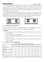
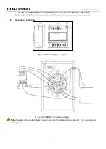
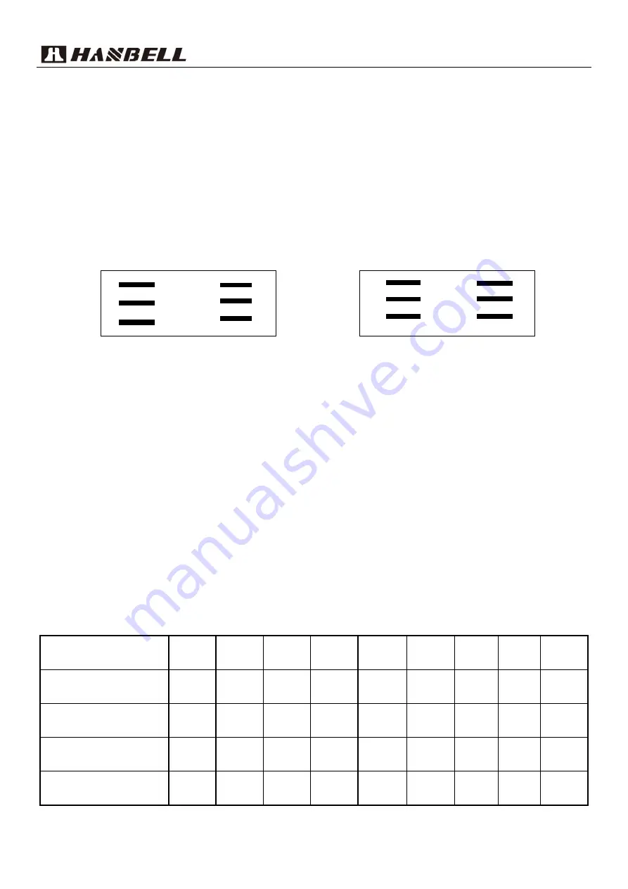
It is suggested that if the difference of the maximum and minimum phase current is bigger than 3% of the
average current during operation, the three-phase power lines can be exchanged as shown in following figures. If the
unbalanced phase does not change with phase modulation, it's not the motor problem. Please turn off the machine
in time and wait the problem to be solved. If it is motor problem, please contact HANBELL.
Standard connection of main power supply line Main power supply line connection during test
2.4.3
Electromagnetic contactor selection
Please refer to the section of contactor in the electrician manual. It is recommended to refer to the AC3
specifications, and to choose the suitable contactor according to the data and the system design.
Suggestions
1.
The set value of the conventional electronic leakage protector should be higher than 50mA (recommend
25mA for moist area).
2.
The grounding resistance should not exceed 500Ω.
3.
If the electronic leakage protector alarm, please check whether the insulation device is normal and its line
setting is correct or not.
4.
Please select the appropriate AC contactor, air switch, and power line according to the maximum operating
current in below table.
2.4.4
Compressor electrical specification table
Table-4 Compressor motor technical data (Power: 380V/50Hz)
Mode
LB
II
-
100(-P)
LB
II
-
140(-P)
LB
II
-
180(-P)
LB
II
-
200(-P)
LB
II
-
230(-P)
LB
II
-
250(-P)
LB
II
-
280(-P)
LB
II
-
360-P
LB
II
-
410-P
Locked rotor current
LRA
(
A
)
218
310
370
508
565
565
710
780
1020
Maximum working current
MCC
(
A
)
57
78
94
114
127
138
151
203
232
KM1, KM2 contactor
(
A
)
40
50
65
90
95
95
115
150
150
Wire selection
(
mm2
)
6
10
16
25
25
35
35
50
50
Locked rotor current: the motor rotor fails to rotate because of heavy load or other reasons, and at this time the
Z
X
Y
7
8
9
U
V
W
1
2
3
Z
X
Y
8
9
7
U
V
W
2
3
1


