LB
II
-PLUS Technical Manual
11
2.3
System application
-PLUS system layout: Single type
Page 1: ...Motor control 21 2 5 Installation and fixation 24 3 Accessory 26 3 1 Accessory list 26 3 2 Oil circuit parts 27 3 3 System parts 29 3 4 Electrical parts 31 4 Maintenance 38 4 1 Items to be checked bef...
Page 2: ...LBII PLUS Technical Manual 2 5 6 LBII 100 280 PLUS Dimension 49 5 7 LBII 100 280 P PLUS Dimension 50 5 8 LBII 360 410 PLUS Dimension 51...
Page 3: ...cess cooling freeze drying and other fields with sufficient competitiveness In general LBII PLUS is a new elite product of Hanbell in the of low temperature application field Compared with normal prod...
Page 4: ...5 248 233 LBII 140 LBII 140 P 139 7 290 275 LBII 180 LBII 180 P 179 7 5 310 295 LBII 200 LBII 200 P 198 10 440 420 LBII 230 LBII 230 P 224 10 460 440 LBII 250 LBII 250 P 257 10 5 464 446 LBII 280 LBII...
Page 5: ...LBII PLUS Technical Manual 5 1 5 Operation range...
Page 6: ...ivided into two structural forms with oil separator and without oil separator LBII 360 410 PLUS have only one structure without oil separator It can be applied to various application fields and differ...
Page 7: ...the motor cooling The effect is particularly obvious at low temperature In order to effectively control the refrigerant quantity that enter into the motor chamber HANBELL designed the scheme to contro...
Page 8: ...is recommended that the high pressure reservoir should be equipped with level switch to prevent the leakage of fluorine after long term operation of the system resulting in insufficient cooling liqui...
Page 9: ...the rotors and the compression chamber and between the male rotor and female rotor to reduce the leakage of the refrigerant gas from the high pressure side to the low pressure side during the compress...
Page 10: ...erefore the oil filter must be installed to the external oil circuit and the pressure difference switch must be installed before and after the filter When the pressure difference value reaches the set...
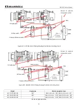
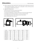
Page 11: ...LBII PLUS Technical Manual 11 2 3 System application LBII PLUS system layout Single type...
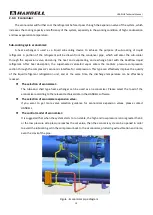
Page 12: ...PLUS system layout Parallel type Figure 8 Basic system configuration Note The motor liquid injection pipe of each compressor in parallel should take liquid from the main circuit pipe independently to...
Page 13: ...h flexible length and it needs to be ensured that the suction and discharge pipeline will not generate stress on the compressor It is suggested to use copper pipes as suction and discharge pipes becau...
Page 14: ...ternal oil circuit system If the compressor operates under low temperature conditions and the lubricating oil does not have extra cooling it will be unable to meet the operation requirements because o...
Page 15: ...ipeline diagram of external oil system Air cooling type The fan accelerates the air flow passes the fin of oil cooler to cool the lubricating oil in the pipeline The suggested system layout is shown i...
Page 16: ...valve Handle valve Water cooling type The cooling water circulates by the pump and takes the heat of the lubricating oil The suggested system layout is shown in following Figure For the pressure diff...
Page 17: ...lecting we must consider the limit oil cooling load in the working condition and consider the size of the oil cooler Configuration suggestion 1 When the system is under normal operation the pressure d...
Page 18: ...in oil circuit 5 8 Branch oil circuit 3 8 LBII 200 280 PLUS 5 8 Main oil circuit 1 1 8 Branch oil circuit 5 8 LBII 360 410 PLUS Main oil circuit 1 1 8 Branch oil circuit 5 8 Oil circuit pipe size tabl...
Page 19: ...gh the compressor s economic interface for compression This type can effectively improve the quality of the liquid refrigerant refrigeration unit and at the same time the discharge temperature can be...
Page 20: ...protection At this time it needs to do condensing pressure control ensuring enough high and low pressure difference can be established within a short period of time to ensure compressor oil supply It...
Page 21: ...separator For parallel system an oil filler and oil relief valve should be installed on the external oil separator to ease the replacement and supplement of lubricant Cannot start the compressor if te...
Page 22: ...taneous operation Rated voltage 10 Frequency Rated frequency 2 Three phase voltage unbalance The unbalanced three phase voltage is mainly caused by unequal distribution of three phase load NEMA The As...
Page 23: ...actor selection Please refer to the section of contactor in the electrician manual It is recommended to refer to the AC3 specifications and to choose the suitable contactor according to the data and t...
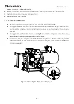
Page 24: ...nstalled directly on the heat exchanger If the compressor must be installed in that way due to condition restriction please ensure the strength of the load bearing structure It is suggested to use a f...
Page 25: ...ompressor installation place and direction shall be easy for oil level check and daily maintenance 4 The installation position shall be strong enough so as not to cause resonance and noise 5 Avoid ins...
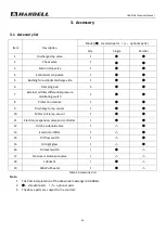
Page 26: ...tial pressure monitoring switch 1 8 Protection module 1 9 Discharge temp sensor 1 10 Motor coil temp sensor 1 11 Electronic expansion valve and controller 1 12 Oil line solenoid valve 1 13 External oi...
Page 27: ...has an external oil separator The specifications of the oil flow switch are shown in the following chart Type Size Connection Applicable model 138 3 8 Thread weld LBII 100 180 PLUS 125 5 8 Thread weld...
Page 28: ...e Connection Applicable model 3 8 Thread Weld LB 100 180 PLUS 5 8 Thread Weld LB 200 410 PLUS 3 2 4 Oil circuit solenoid valve Figure Oil circuit solenoid valve diagram Direction arrow at the bottom M...
Page 29: ...P should be connected to the compressor oil filter flange angle valve When the oil resistance is greater than the set value 1 5bar the pressure difference switch will be activated OFF to cut off the c...
Page 30: ...valve specification Max working pressure Strength test gas pressure Temperature range 28 bar 35 bar 50 150 3 3 2 Damping pad Function To reduce the additional vibration and noise during compressor op...
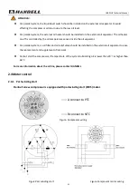
Page 31: ...ctivated and remain to be activated for 5 seconds Motor phase being abnormal or motor being under phase will cause the protection module to be disconnected and locked In order to avoid the tripping ca...
Page 32: ...signal light is for convenient fast and easy maintenance the signal is composed of red and orange The current state of light flashing depends on the number of pulse flashes Signal is as below Pause 1...
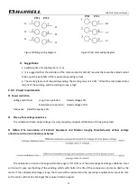
Page 33: ...r to test the resistance between M1 and M2 If it is blocked the protector needs to be replaced E Appearance and wiring Figure INT69 HBY Diagnose diagram Figure INT69 HBY PTC connection diagram Note Th...
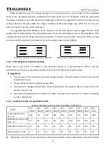
Page 34: ...hed table 3 Normal operation relay M2 and M1 are disconnected M2 and M0 are closed When the motor temperature is higher than 95 C M2 and M1 are closed M2 and M0 are disconnected and can be connected a...
Page 35: ...reinforced fiber Installation By Screw Size Unit mm Weight Around 200g Standard GB14048 1 2016 GB17626 2008 C Appearance and wiring Dimension Function Description Note NTC Fault Normal condition M0 a...
Page 36: ...5 101 18 69 10 5 45 33 8 80 56 12 15 79 15 49 102 18 84 11 5 60 34 8 95 57 12 29 80 15 64 103 18 98 12 5 75 35 9 09 58 12 44 81 15 78 104 19 13 13 5 89 36 9 24 59 12 58 82 15 93 105 19 27 14 6 04 37 9...
Page 37: ...33 6 21 53 21 15 20 78 47 4 68 4 59 4 51 88 1 38 1 34 1 30 7 20 64 20 30 19 95 48 4 52 4 44 4 36 89 1 34 1 30 1 26 8 19 81 19 48 19 15 49 4 38 4 30 4 22 90 1 31 1 27 1 23 9 19 01 18 70 18 39 50 4 24 4...
Page 38: ...angle so as to avoid the damage of the insulation skin It should be equipped with a terminal box and bolt 5 Make sure it is installed 3 Pipeline system 1 Whether the pipe is secured or not 2 Make sur...
Page 39: ...g and fastening of the wire and the sight line of the oil circuit When the condensing unit is in operation special attention should be paid to its auxiliary equipment as well as the maintenance schedu...
Page 40: ...lts analysis Faults Possible reasons Compressor motor coil temperature protection jump off 1 The motor load is too large the cooling is insufficient or the motor liquid spray solenoid valve is invalid...
Page 41: ...on is not made 4 The suction filter is frozen or dirty 5 The evaporator is too small 6 Low pressure protection setting problem System high pressure alarm 1 Too much refrigerant 2 The effect of heat ex...
Page 42: ...chnical Manual 42 5 Appearance and functions 5 1 Appearance structure External structure single machine LBII 100 280 PLUS Low temperature screw compressor external structure 1 12 2 3 4 5 6 7 8 10 9 11...
Page 43: ...LBII PLUS Technical Manual 43 LBII 360 410 PLUS Low temperature screw compressor external structure 1 2 13 4 6 3 14...
Page 44: ...1 2 3 5 High pressure detective valve 1 4 1 4 1 4 1 4 1 4 6 Oil circuit sight glass 7 Low oil level sight glass 8 Oil inlet connector 3 8 3 8 5 8 5 8 5 8 9 Oil outlet connector 3 8 5 8 10 Oil block p...
Page 45: ...Discharge Copper Steel Suction Copper Steel Economizer Main oil inlet Main oil return Motor liquid injection port LBII 100 1 1 2 42 49 3 2 55 61 3 22 Welding 3 8 9 7 3 8 9 7 1 4 6 5 LBII 140 1 1 2 2 2...
Page 46: ...28 LBII 410 P PLUS Discharge Copper 3 1 8 66 120 45 80 5 90 Steel 3 90 2 103 Suction Copper 3 5 8 76 145 50 93 103 Steel 4 110 128 5 3 LBII 100 280 PLUS Dimension LBII PLUS HANBELL Model A B C D E F G...
Page 47: ...I J K LBII 100 P 1004 562 18 129 5 254 163 5 338 303 300 395 133 LBII 140 P 1017 597 18 117 241 177 339 308 350 402 5 104 LBII 180 P 1083 611 18 117 6 241 177 405 308 350 402 5 104 LBII 200 P 1186 63...
Page 48: ...al 48 5 5 LBII 360 410 PLUS Dimension A B M L D E F H I J K G Model A B C D E F G H I J K L M LBII 360 1137 360 18 397 147 98 384 5 495 342 5 538 939 301 408 LBII 410 1237 360 18 397 156 106 465 8 576...
Page 49: ...lock pin 4 Low pressure filling valve 1 4 16 Oil outlet connector 5 Low pressure stop valve 17 Angle valve 1 4 6 Motor chamber angle valve 1 4 18 High oil level sight glass 7 Terminal box IP54 19 Disc...
Page 50: ...ge stop valve 14 Discharge check valve 4 Solenoid valve 15 Suction check valve 5 Suction stop valve 16 Oil circuit sight glass 6 Filling valve 1 4 17 Oil inlet connector 7 Low pressure side angle valv...
Page 51: ...3 8 Economizer flange 1 1 8 2 Discharge stop valve LBII360 2 1 2 LBII410 3 9 Suction check valve 4 3 Filling valve 1 4 10 Oil inlet connector 5 8 4 Low pressure side angle valve 1 4 11 Discharge temp...