LT-S-(L) Technical manual
Stepless type capacity modulation and water temperature control
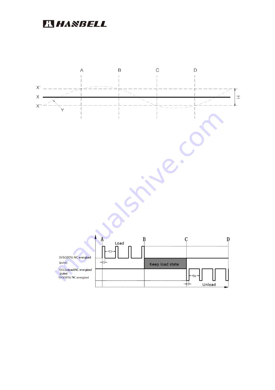
Below picture shows the load control of single compressor in the application of
stepless type capacity modulation.
Figure 3-12. Stepless Type Capacity Modulation
★
Note
:
X′Upper Limit
;
X
〞
Lower Limit
;
X Set Point
;
H Control Range
;
Y Actual valve
Description:
The actual water temperature exceeds the upper limit between A & B. It
means the compressor ought to unload until the actual value is within the
control range.
The real value is smaller than the bottom line between C & D. It means the
required cooling capacity is decreasing and the compressor needs to be
unloaded until the real value returns to the control range.
Figure 3-13. Solenoid Valve Action Intervals-Stepless Type
★
Note
:
For detail stepless type capacity modulation control logic, please refer to
Table 3-2
Load/Unload functions between A and B, C and D.
Energized
:
Solenoid valve is powered and energized
Close
:
Solenoid valve is not energized
T1
,
T3
:
Pulse time 0.5~1.5 seconds
T2
,
T4
:
Pause time 10~20 seconds
Time


