12
4. Compressor lifting and installation
4.1 Compressor lifting
Each HANBELL screw compressor has been carefully tested at the factory and every precautionary measures have
been taken to make sure that compressors will keep in perfect condition when reaching customers’ work. After the
compressor arrives at your warehouse, please check if its crate is kept in good condition and check all the compressor
accessories with shipping documents to see if there is any discrepancy.
When lifting the compressor, it is recommended to use a steel chain or steel cable which can be used for loading
capacity of 2000kgf as shown in the figure below. Make sure that chains, cables or other lifting equipments are properly
positioned to protect the compressor and its accessories from damaging. Keep the compressor in horizontal position
when lifting, and prevent it from crashing or falling on the ground, hitting the wall or any other accident that may
damage it or its accessories.
Figure 8
Lifting the compressor with steel chains or steel cables
Figure 9
Lifting the compressor with safety ropes
4.2 Mounting the compressor
The installation of the compressor in the refrigeration system should be made accessible and make sure that the chiller
base or site is far enough from the heat source to prevent heat radiation. The compressor should also be installed as
close as possible to electrical power supply for easy connection. Keep good ventilation and low humidity condition at
the site. Make sure that the frame or support is strong enough to prevent excessive vibration and noise while the
compressor is running and must reserve enough space for future overhauling work.
The compressor must be installed horizontally and in order to prevent excessive vibration transferred by the structure
and piping of the chiller while in operation, cushion or anti-vibration pads should be installed. The installation of the
anti-vibration pads is shown in Figure 10. The screws should only be tightened until slight deformation of the rubber
pads is visible.
※
It is strongly recommended to position the compressor higher than the evaporator
Compressor mounting pad
Fixed Bolt
Anti-Vibration Rubber
(6-15mm)
Figure 10 Installation of anti-vibration pads
Summary of Contents for RC2-AV Series
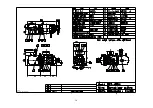
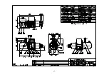
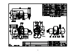
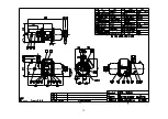
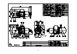
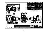
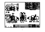
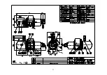
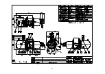
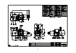
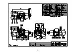
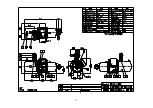
Page 15: ...4 3 RC2 AV series compressor outline drawings...
Page 16: ...15...
Page 17: ...16 UNIT SI mm Imperial in...
Page 18: ...17...
Page 19: ...18...
Page 20: ...19...
Page 21: ...20...
Page 22: ...21...
Page 23: ...22...
Page 24: ...23...
Page 25: ...24...
Page 26: ...25...
Page 27: ...26...
Page 28: ...27...
Page 29: ...28...
Page 30: ...29...
Page 31: ...30...
Page 32: ...31...
Page 33: ...32...
Page 34: ...33 SI mm Imperial in UNIT...
Page 35: ...34...
Page 36: ...35...
Page 37: ...36...


