42
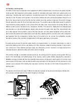
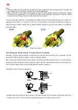
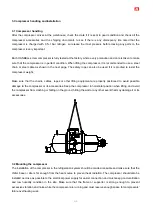
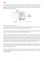
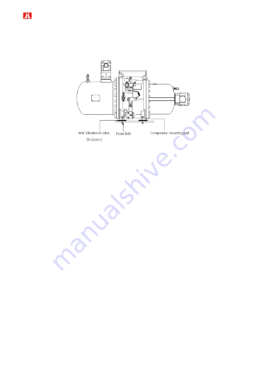
The compressor must be installed horizontally and in order to prevent excessive vibration transferred by the
structure and piping of the chiller while in operation, the cushion or anti-vibration pad should be installed. The
installation of the anti-vibration pad is shown in the figure below. The screws should only be tightened until slight
deformation of the rubber pad is visible.
Attention on the compressor piping works
The unsuitable piping works done to the compressor could cause abnormal vibration and noise which might
damage the compressor. Take notice to the following points to prevent this situation:
1. Cleanliness of the system should be kept after welding the piping to avoid any swarf or debris contained inside
the system as it may cause serious damage to the compressor during operation.
2. In order to reduce the vibration on the piping tubes, it is recommended to use copper tube to be the suction and
discharge piping tubes. Copper tubes are better to minimize the vibration in the piping while the compressor is in
operation. In case steel tubes are used in piping system, then the suitable welding works are very important to
avoid any stress in the piping. This inner stress can cause harmonic vibration and noise which will reduce the
compressor life. If a large-caliber copper tube is not easily accessible and a steel tube is used instead in suction
port, Hanbell recommends using a copper tube in discharge port to minimize abnormal vibration and noise.
3. Remove the oxidized impurities, swarf or debris caused by welding in the piping tubes. If these foreign matters
are sunk into the compressor, the oil filter might be clogged resulting in the malfunctioning of lubrication system,
bearings and capacity control system.
4. Suction and discharge flanges are forged steel and it can be welded directly with piping connectors. After
welding the flanges and pipes, it must be cooled down by ambient air. Do not use water to cool it down. Water
quenching is prohibited.
Summary of Contents for RC2-F Series
Page 6: ...5 2 2 Compressor outline...
Page 7: ...6...
Page 8: ...7...
Page 9: ...8...
Page 10: ...9...
Page 11: ...10...
Page 12: ...11...
Page 13: ...12...
Page 14: ...13...
Page 15: ...14...
Page 16: ...15...
Page 17: ...16...
Page 18: ...17...
Page 19: ...18...
Page 20: ...19...
Page 21: ...20...
Page 22: ...21...
Page 23: ...22...
Page 24: ...23...
Page 25: ...24...
Page 26: ...25...
Page 27: ...26...
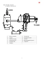
Page 85: ...84 Horizontal External Oil Separator OS80 Horizontal External Oil Separator OS100 OS125 OS150...

