Technical Manual
VERSION 2.0 -10-18-2018
63
5. Electrical data and design
5.1 Motor design
HANBELL RC2 series screw compressors are fitted with Y∆ motor as standard. But ∆/∆∆ motor (Part Winding
Starting – PWS) is also available for model RC2100A ~ RC2580A & RC2100B ~ RC2580B.
i.e. ●RC2100A ~ RC2580A & RC2100B ~ RC2580B both Y∆ motor and ∆/∆∆ motor are available.
●RC2620A ~ RC21530A & RC2620B ~ RC21530B only Y∆ motor are available.
Y∆ Starting
Y∆ motor connects motor coil by Y connection during starting therefore reducing voltage on coils to 1/√3 of input
△
voltage and reconnects motor coil by connection after starting. By doing so, we can decrease starting current
thorough voltage drop, i.e., socalled voltagedrop starting.
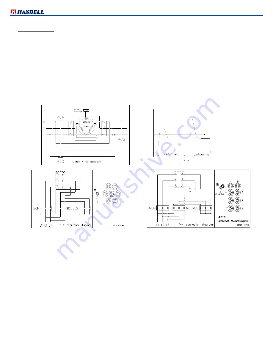
Y∆ motor connection method is shown in the following motor wiring diagram:
In Y connection, MCM, MCS are inductive while motor leads Z,X,Y are tied together as a neutral connecting as Y
fashion. A few seconds later (3~5 sec is recommended), MCM, MCS become deductive. Around 0.25 sec later,
MCM,MCD are inductive,
△
it turns out run connection.
Full load Amper
Starting
Current
Time
(AMP)
Y shift time 0.25~0.5sec
Figure 54 Y∆ Starting diagram
Attention! : After Y start, MCM & MCS are deductive for 0.25 sec and then MCM & MCD are inductive for ∆ run. Within
as transient as 0.25 sec, pseudo short circuit might occur due to inappropriate action of contactors, causing trip of
compressors. When it occurs, we recommend usage of adjustable Y∆ dedicated timer or slightly lengthen span of
time for MCM, MCS deduction MCM, MCD reinduction from 0.25 sec to 0.5 sec max directly in micro controller or
PLC program. Please refer to Y∆ shift time diagram for details. Because motor is not powered during Y∆ shift,
shorter Y∆ shift span is suggested to prevent second start due to decreased rotation speed. However, if Y∆ shift
span is too short, aforementioned pseudo short circuit might occur.
Characteristics of Y∆ Starting
1. Starting current in Y connection is 1/3 of lock rotor ampere.
2. Starting torque in Y connection is 1/3 of lock rotor torque.
3. Acceleration of motor rotor becomes smaller at fullload starting, therefore compressors require starting at partial
load.
B:Pt100 / Pt1000(Option)
A:PTC
A
Earth Bolt
B
V
W
Y
X
Z
U
Summary of Contents for RC2 Series
Page 24: ...Technical Manual VERSION 2 0 10 18 2018 24 UNIT SI mm Imperial in UNIT SI mm Imperial in ...
Page 25: ...Technical Manual VERSION 2 0 10 18 2018 25 SI mm Imperial in UNIT UNIT SI mm Imperial in ...
Page 26: ...Technical Manual VERSION 2 0 10 18 2018 26 SI mm Imperial in UNIT UNIT SI mm Imperial in ...
Page 27: ...Technical Manual VERSION 2 0 10 18 2018 27 UNIT SI mm Imperial in ...
Page 28: ...Technical Manual VERSION 2 0 10 18 2018 28 ...
Page 29: ...Technical Manual VERSION 2 0 10 18 2018 29 UNIT SI mm Imperial in ...
Page 30: ...Technical Manual VERSION 2 0 10 18 2018 30 ...
Page 31: ...Technical Manual VERSION 2 0 10 18 2018 31 ...
Page 32: ...Technical Manual VERSION 2 0 10 18 2018 32 ...
Page 33: ...Technical Manual VERSION 2 0 10 18 2018 33 ...
Page 34: ...Technical Manual VERSION 2 0 10 18 2018 34 UNIT SI mm Imperial in ...
Page 35: ...Technical Manual VERSION 2 0 10 18 2018 35 2 RC2 B outline drawings ...
Page 36: ...Technical Manual VERSION 2 0 10 18 2018 36 ...
Page 37: ...Technical Manual VERSION 2 0 10 18 2018 37 ...
Page 38: ...Technical Manual VERSION 2 0 10 18 2018 38 ...
Page 39: ...Technical Manual VERSION 2 0 10 18 2018 39 ...
Page 40: ...Technical Manual VERSION 2 0 10 18 2018 40 ...
Page 41: ...Technical Manual VERSION 2 0 10 18 2018 41 ...
Page 42: ...Technical Manual VERSION 2 0 10 18 2018 42 ...
Page 43: ...Technical Manual VERSION 2 0 10 18 2018 43 ...
Page 44: ...Technical Manual VERSION 2 0 10 18 2018 44 SI mm Imperial in UNIT ...
Page 60: ...Technical Manual VERSION 2 0 10 18 2018 60 ...
Page 83: ...Technical Manual VERSION 2 0 10 18 2018 83 NOTES ...


