Technical Manual
VERSION 2.0 -10-18-2018
64
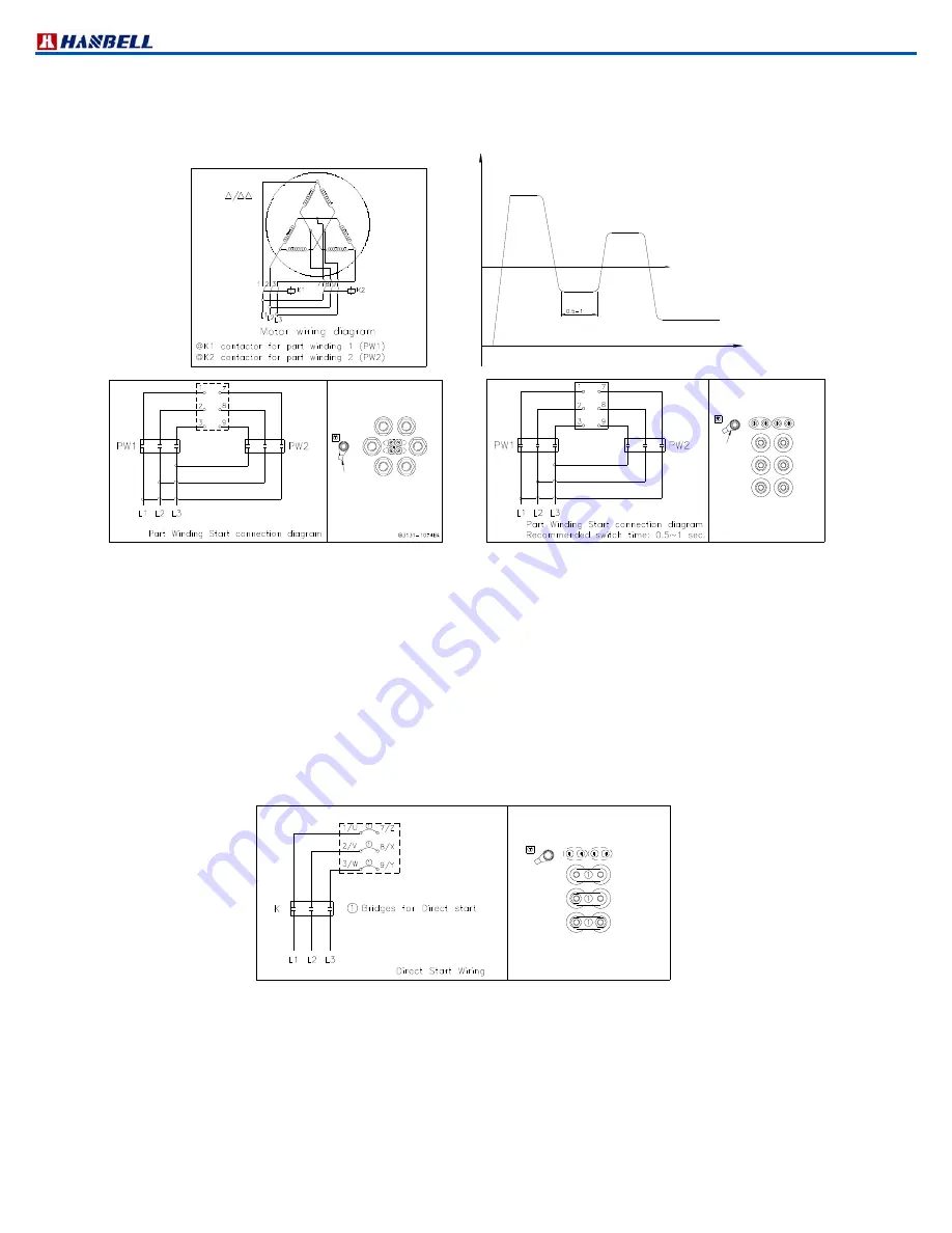
∆/∆∆ (PW) starting
RC2100A ~ RC2580A & RC2100B ~ RC2580B are available to be fitted with PWS motor for customer’s application
as an optional accessory. Please refer to the follow diagram for the wiring of PWS motor.
Full load Amper
Starting Current
Time
(AMP)
sec
PW2:7,8,9 B:Pt100 / Pt1000
(Option)
PW1:1,2,3
9
3
A:PTC
2
8
Earth Bolt
7
1
A
B
Figure 55 ∆/∆∆ (PW) starting diagram
The selection of both of the motor contactors (k1 / k2) is each for approx. 60% of the max. running current. The
recommended time delay of the switching relay k1 is to be set at 0.5 second and not more than 1 second.
PWS Starting features
The starting current is around 40% ~ 70% of fullwinding Locked Rotor Current. It depends on the design and motor
size, and low starting torque.
Direct on line features
The starting equipment consists of only a main contactor and thermal or electronic overload relay. During a directon
line start, the starting torque is very high, and is higher than necessary for most applications. The disadvantage with
this method is that it gives the highest possible starting current. Please refer to the follow diagram for the wiring of DOL
starting
B:Pt100 / Pt1000
2/V
3/W
A:PTC
(Option)
8/X
9/Y
Earth Bolt
1/U
A
B
7/Z
Figure 56 DOL starting diagram
Soft starting features
A soft starter is different from other starting methods in characteristics. It has thyristors in the main circuit, and the
motor voltage is regulated with a printed circuit board. The soft starter’s advantage is that when the motor voltage is
low during start, the starting current and starting torque is also low. Please refer to the following diagram for wiring of
soft starting.
PW2:7,8,9
PW1:1,2,3
(Option)
A:PTC
B:Pt100 / Pt1000
A
Earth Bolt
B
3
9
7
1
2
8
Summary of Contents for RC2 Series
Page 24: ...Technical Manual VERSION 2 0 10 18 2018 24 UNIT SI mm Imperial in UNIT SI mm Imperial in ...
Page 25: ...Technical Manual VERSION 2 0 10 18 2018 25 SI mm Imperial in UNIT UNIT SI mm Imperial in ...
Page 26: ...Technical Manual VERSION 2 0 10 18 2018 26 SI mm Imperial in UNIT UNIT SI mm Imperial in ...
Page 27: ...Technical Manual VERSION 2 0 10 18 2018 27 UNIT SI mm Imperial in ...
Page 28: ...Technical Manual VERSION 2 0 10 18 2018 28 ...
Page 29: ...Technical Manual VERSION 2 0 10 18 2018 29 UNIT SI mm Imperial in ...
Page 30: ...Technical Manual VERSION 2 0 10 18 2018 30 ...
Page 31: ...Technical Manual VERSION 2 0 10 18 2018 31 ...
Page 32: ...Technical Manual VERSION 2 0 10 18 2018 32 ...
Page 33: ...Technical Manual VERSION 2 0 10 18 2018 33 ...
Page 34: ...Technical Manual VERSION 2 0 10 18 2018 34 UNIT SI mm Imperial in ...
Page 35: ...Technical Manual VERSION 2 0 10 18 2018 35 2 RC2 B outline drawings ...
Page 36: ...Technical Manual VERSION 2 0 10 18 2018 36 ...
Page 37: ...Technical Manual VERSION 2 0 10 18 2018 37 ...
Page 38: ...Technical Manual VERSION 2 0 10 18 2018 38 ...
Page 39: ...Technical Manual VERSION 2 0 10 18 2018 39 ...
Page 40: ...Technical Manual VERSION 2 0 10 18 2018 40 ...
Page 41: ...Technical Manual VERSION 2 0 10 18 2018 41 ...
Page 42: ...Technical Manual VERSION 2 0 10 18 2018 42 ...
Page 43: ...Technical Manual VERSION 2 0 10 18 2018 43 ...
Page 44: ...Technical Manual VERSION 2 0 10 18 2018 44 SI mm Imperial in UNIT ...
Page 60: ...Technical Manual VERSION 2 0 10 18 2018 60 ...
Page 83: ...Technical Manual VERSION 2 0 10 18 2018 83 NOTES ...


