40
Vol. 2.6 © 2020 Hanbell Precise Machinery Co., Ltd. All rights reserved
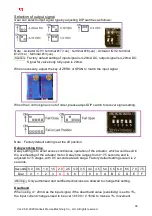
Local Operation Mode
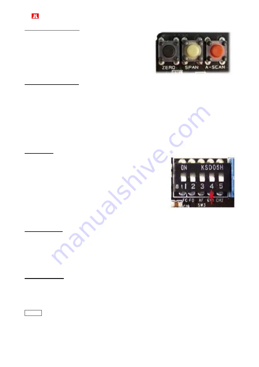
This feature allows for temporary local operation by use of
the Zero/Close and Span/Open buttons on the PCU board
to open and close the guide vanes. To access this feature,
simultaneously push the Zero and Span buttons, hold for
two seconds, and release. The yellow Fault LED will be lit
to indicate Local operation mode. (If there is no operation
occurs within 15 seconds, the PCU will default to setpoint
control).
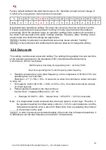
Automatic Calibration
This feature allows for automatic calibration of the PCU card to the preset limits, without the need
for a signal generator. To access this feature, press the A-Scan button one time. The white Auto
Scan LED will flash. The unit will then automatically stroke to the close limit, pause, then stroke to
the open limit and stop. The PCU will now be calibrated.
Note
:
1. Actuator is calibrated at the factory, and settings are stored in non-volatile memory. No
recalibration required unless the limits are changed.
2. When Actuator is in operation, the operating mode is repositioned to automatic mode.
Do not use Manual mode unless under troubleshooting situations. Using manual mode
is not recommended at normal conditions.
Split Range
This feature allows a range of set points for full open and full close
positions.
Close: 3 to 8mA DC
Open: 16 to 21mA DC
For example: If the user would like to assign 5mA to the fully
closed position, supply a 5mA signal and then allow the actuator to
move to the corresponding position. Move switch 4 (CH1) to the
on position, and press the Zero button one time. The actuator
acknowledges that position as fully closed and transmits 4mA.
Push the Span button to set the fully open position. Once the setting is complete, move switch 4
down to the off position.
Reverse Acting
Standard operation is clockwise rotation of the actuator to close. When reverse action, or
counterclockwise rotation to close is required, move switch 5 (CH2) to the on position (up). Move
actuator to mid position and push A-scan button. Supply signal and check rotation.
Switch 5 on (up) = 20mA Full Close
Switch 5 off (down) = 4mA Full Close
4mA Full Open
20mA Full Close
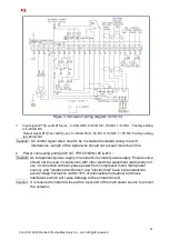
3.2.5 Wiring
The terminals of the control elements in the actuator are connected inside the housing. Remove the
housing and connect the cable to the terminals. The connection method is shown in Figure 3.4 and
Figure 3.4.1. Please check if the power supply is in proper voltage. When all terminals are properly
connected, please adjust to half open level with manual control and test the grounding.
Caution
:
Please turn off all power services before attempting to perform maintenance and
wiring of actuator. Before dismantling the actuator, make sure that the IGV is in
fully close and not pressurized condition.


