53
Vol. 2.6 © 2020 Hanbell Precise Machinery Co., Ltd. All rights reserved
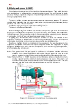
3.4 Hot gas bypass (HGBP)
Centrifugal compressors are of non-positive displacement types. They raise pressure
and temperature of refrigerant by converting kinetic energy into an increase in static
pressure. Hot gas bypass is to bypass or liquid refrigerant from condenser into evaporator
through a proportional valve.
Function 1: When the load reaches certain value the surge would happen. To continue
the low load operation, the hot gas by pass valve can be opened to increase suction
pressure and lower compression ratio.
Function 2: Apply during start up to lower starting current.
Function 3: Unloading modulation
Because hot gas bypass method is to transfer compressed gas from the condenser
(high-pressure side) to the evaporator (low-pressure side), it should be noticed that this
volume flow might make enormous noise. It is recommended to enlarge the inner diameter
of piping after the HGBP valve to keep flow speed under 10 m/sec.
In piping, the proportional valve should be installed as close as possible to the
evaporator, and also at another side of suction entry (motor side), to lower the noises at
suction side. Setting the piping on suction pipe can also prevent liquid strike.
Besides, a muffler should be installed at the evaporator. Hot gas bypasses to the
evaporator should be prevented from liquid refrigerant inside the evaporator. If liquid
refrigerant splashes and sucks into the compressor, it will result in liquid compression,
which damages the compressor.
Note1: The system with hot gas bypass is inefficient. It should be avoided whenever
possible. Many system applications still require hot gas bypass in order to avoid
surge or maintain constant chilled water temperatures from zero load to full load.
Note2: Required flow for HGBP depends on the difference between required minimum
cooling capacity and the minimum load compressor can reach. If the IGV is at
minimum opening and cooling capacity is 50%, and end user needs 20%. The pipe
diameter and flow need to be considered based on the 30% difference.
Figure 3.7 Refrigerant Circuit & Motor Cooling systems

