54
Vol. 2.6 © 2020 Hanbell Precise Machinery Co., Ltd. All rights reserved
3.5 Proportional valve
Single IGV model:
When the compressor operates at low pressure ratio with IGV1
≤
10%, the inlet flow will have higher
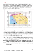
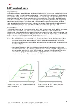
pressure loss due to the angle of IGVs. As shown in Figure 3.8(a), from point to 9 to 1 the pressure
loss becomes larger, leading to a lower intermediate pressure closing to evaporation pressure and
the economizer may have higher liquid level due to higher difficulty in controlling expansion valve
and orifice plate at low pressure end. As a result, liquid refrigerant may be drawn into compressor
intermediate inlet (ECO port). Therefore, it is recommended to install an intermediate pressure
valve between ECO port and economizer, near the compressor. Close the intermediate pressure
valve when IGV’s opening <10%, while fully open the valve when IGV opening is
≥
10%.
Dual IGV Model:
For dual IGV models, IGV2 is adjustable radial guide vane. IGV2 opening can be used to control the
pressure in the economizer to maintain a certain pressure difference between intermediate
pressure and low pressure when operating in low pressure ratio. Thus, the intermediate inlet is less
likely to suffer from the phenomenon of liquid absorption, as shown in Figure 3.8(b), so double IGV
model users do not need additional intermediate pressure valve.
Note: 1. For dual IGV models, intermediate inlet is less likely to have liquid absorption issue, thus
the minimum operating opening is
≥
5%. The link relationship between IGV1 and IGV2
should be applied by Hanbell to ensure that the compressor intermediate pressure control
is at the best point.
2. Intermediate pressure valve: Due to part load requirements (such as pure orifice plate
expansion valve unit), some unit designs require lower economizer (flash tank) pressure to
ensure smooth discharge of motor cooling liquid. In this case, the intermediate pressure
valve requires proportional control and thus, a proportional valve should be used.
Otherwise, an ON-OFF type shut-off valve is applicable.
Figure 3.8 (a) Single IGV enthalpy diagram of Figure 3.8 (b) Dual IGV enthalpy diagram
2-stage compression of 2-stage compression


