56
Vol. 2.6 © 2020 Hanbell Precise Machinery Co., Ltd. All rights reserved
Chapter 4. Lubrication system
4.1 Oil circuit
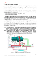
Lubricant is driven by built-in oil pump in the compressor. Oil passes front / back
bearings of motors since gears and bearings are around the high-speed shaft for
lubrication. The oil system consists of an oil pump, a relief valve, an oil filter, oil cooler and
other control valves.
Figure 4.1 Schematic diagram of oil piping
After lubricant is pressurized by built-in oil pump, it passes the relief valve for modulation
of pressure and flows through pipe 1. The oil circuit is then divided into two passages, Pipe
2 & 3, which is after the oil cooler and the oil filter. Oil in pipe 3 lubricates bearings in the
back of the motor and returns to the oil tank by pipe 3’. Oil in Pipe 2 enters gear box on the
top, and lubricates bearings in front of the motor, the gears, and the front/ back bearings,
which are around the high-speed shaft, and returns to the oil tank finally.
Caution
:
RT-series centrifugal compressor uses positive displacement gear pumps which release
pulsating wave at the discharge of the oil pump. Therefore, a buffer tube and a steel wire hose
(length> 40cm) should be added at the outlet of the oil pump to absorb the shock.
Definition:
R1: Resistance in pipe, R1=P1-P2. It includes pressure drop in pipe itself, oil
cooler, and oil filter. Please pay attention to the pressure sensor installing point.
R2
:
Internal resistance in compressor. Its fixed value 2.0~2.2 bar indicates the
necessary pressure difference for compressor lubrication.
Pipeline resistance (R1) protection
Oil filter is the only component in the pipeline that has variable resistance while the rests are
constants, thus the pressure difference of P1-P2 should be monitored to prevent lack of lubrication
caused by oil filter blockage.


