[文件標題]
[日期]
23
Vol. 1.2 © 2020 Hanbell Precise Machinery Co., Ltd.
All rights reserved
4.3 Motor Temperature Control
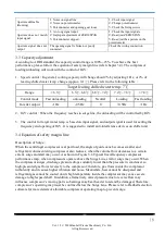
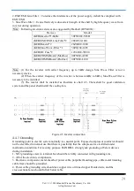
There are six set of Pt100 installed in motor winding to monitor motor temperature and suggest control
logic is listed below:
1.
※
Motor Temp.
:
T
>
90
℃
(alarm)
;
T > 100
℃
(tripping)
※
Bearing Temp.
:
T
>
75
℃
(alarm)
;
T > 85
℃
(tripping)
※
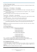
Liquid injection should be turned on if the alarm from motor temp. or bearing temp. alarm is on
(refer figure4.4)
※
The auxiliary liquid solenoid valve can be closed when the motor temperature
≦
80
℃
or magnetic
bearing temperature
≦65℃.
※
Bearing cooling (gas type) stop valve should be open when compressor running.
2.
※
Shaft stretch
:
>300µ m(alarm)
;
>400µm(tripping)
※
The auxiliary liquid solenoid should be opened when the Shaft stretch is greater than the warning
value.
※
When the shaft stretch
≦
250
μ
m can be turn off auxiliary liquid solenoid.
Please consult Hanbell representatives for details on Shaft stretch calculation.
Note: The controller must warning when one of Pt100 sensor detecting the temperature higher than
upon definition temperature, and compressor must stop until the reason has been found out.
Remark
:
Six sets of Pt100 are showing in different color with red, white, black, yellow, blue, and gray.
Common line is in green.
4.4 Motor connection
4.4.1
Voltage & Frequency
The RTM compressor is working on following power supply range:
380V±5%(342V~418V)
400V±5%(360V~440V)
460V±5%(414V~506V)
Table 4.1 Rated Voltage Supply Range
50 Hz±3%(47Hz~53Hz)
60 Hz±3%(57Hz~63Hz)
Table 4.2 Rated Frequency Supply Range
Note
:
1. Frequency is applied for power generator, not compressor motor frequency.
2. The chart above is suggested for the compressor and its accessory such as inverter. For other
electronic components, please double check their designed power supply.
4.4.2 Components of inverter
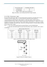
The connection of inverter is showing in figure 4.5
:
1. No-Fuse Breaker(NFB)
:
To protect an electrical circuit from damage caused by excess current, the
selection of the NFB shall be based on the current under full load condition. 600DCV/16A is
suggested
Note
:
Full load current is calculated when reactor is applied.


