


HQ Sixteen
™
User Manual 1.6
Page 3
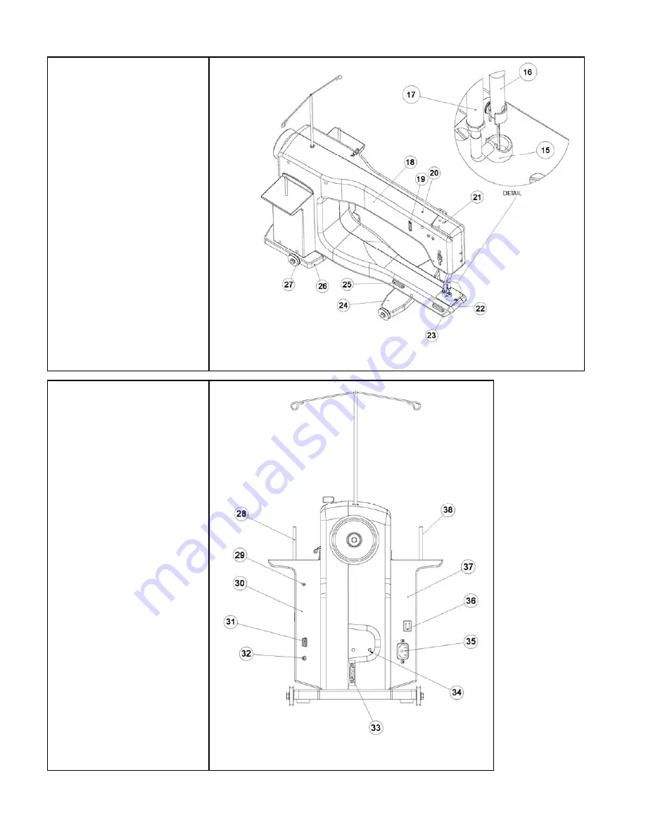
Diagram C
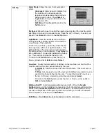
Diagram B
Back Side
Diagram B
15. Hopping Foot
16. Needle Bar
17. Presser Bar
18. Back Casing/Frame
19. Front Handle Serial Port
Connector
20. Top Laser Stylus Post
Hole
21. Front Threaded Handle
Holes
22. Bobbin Assembly
23. Needle Plate
24. Front Wheel Base
25. Oval Position Guides
26. Rear Wheel Base
27. Wheels (4)
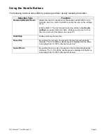
Rear
Diagram C
28. Spool Pin 1
29. Laser Stylus Power
Connector
30. Front Electronic Control
Pod
31. Serial Port for Stitch
Regulator
or Foot Control
32. Foot Pedal Connector
33. Rear Handle Bar Serial
Port
34. Rear Threaded Handle
Holes
35. Power Cord Connector
36. On/Off Switch
37. Back Power Pod
38. Spool Pin 2
Summary of Contents for HQSixteen
Page 24: ...www HandiQuilter com ...


