3
3
C
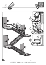
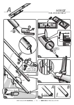
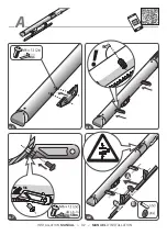
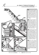
[1]Position the rail on the stairs.
The distance to the wall is mentioned
on the enclosed drawing. [2]After in-
stalling of the joint according to the
manual [page 8/9], do an extra check
on the alignment of domexstrip/tooth-
rail. [3]Fix two supports{A} on the bot-
tom/topfloor according to the manual
[page 24]. [4]In case of rail A2 you
start with the lower support at the
bottomfloor and the first support at
the toplanding.
UK
A-RAILS [ADDITIONAL]
[1]Plaats de rail op de trap. De
afstand tot de wand is vermeld in de
bijgevoegde tekening. [2]Na het in-
stalleren van de koppeling volgens
de handleiding [pagina 8/9], doe een
extra check op de uitlijning van do-
mexstrip/tootrack. [3]Bevestig twee
steunen{A} op de vloer/verdieping
volgens de handleiding, pagina 24.
[4]In geval van rail A2 begin je met
de onderste steun op de vloer en de
eerste steun op de verdieping.
[1]Positionieren Sie die Schiene
auf der Treppe. Der Abstand zur Wand
ist auf der beiliegende Zeichnung er-
wähnt. [2]Nach die Installation des
Gelenks nach die Anleitung[Seite 8/9],
machen Sie ein extra Kontrolle auf
der Ausrichtung vom domex/Zahn-
stange. [3]Befestigen Sie zwei Stüt-
zen{A} auf der Boden/Etage nach
der Anleitung [Seite 24]. [4]Im Falle
einer Schiene A2 fangen Sie an mit
der unterer Stütze auf der Boden und
der ersten Stütze auf den Etagen.
[1]Placez le rail sur l’ escaliers.
La distance au mur est mentionné
sur le dessin ci-joint. [2]Après l'instal-
lation du joint conformément au ma-
nuel [la page 8/9], faire un contrôle
supplémentaire sur le aligne de do-
mex/crémailière. [3]Fixez deux sup-
ports{A} sur le sol/1 étage selon le
manuel [page 24]. [4]En cas de rail
A2 vous commencez avec le support
inférieur au sol et le premier support
à l’étage.
DU
FR
NL
A-RAILS [SUPPLÉMENTAIRES]
?
A
A
A
A
2x
3x
3x
3x
A1
A2
A
B
C
C
C
B
A
A
1
3
4
2
INSTALLATION
MANUAL
> 35 <
MANUEL
D’INSTALLATION
Summary of Contents for FREECURVE MONORAIL
Page 6: ...FSR30021 1 2 1 INSTALLATION MANUAL 4 MANUEL D INSTALLATION...
Page 11: ...2 19 2 20 2 18 2 17 2 INSTALLATION MANUAL 9 MANUEL D INSTALLATION...
Page 13: ...B A C 3 3 4 3 3 3 2 3 1 INSTALLATION MANUAL 11 MANUEL D INSTALLATION...
Page 14: ...3 12 Ah 8 Ah 12 Ah 8 Ah 3 8 3 7 3 6 3 5 INSTALLATION MANUAL 12 MANUEL D INSTALLATION...
Page 16: ...3 15 3 14 3 13 3 12 3 10 INSTALLATION MANUAL 14 MANUEL D INSTALLATION...
Page 19: ...CHILD 4 mm 3 26 3 23 3 24 3 25 3 FR 868MHz INSTALLATION MANUAL 17 MANUEL D INSTALLATION...
Page 22: ...STOP CLICK OPTIONAL 3mm A B C 4 9 4 10 4 INSTALLATION MANUAL 20 MANUEL D INSTALLATION...
Page 23: ...2 5 mm 4 4 11 4 12 4 13 4 14 4 15 4 16 INSTALLATION MANUAL 21 MANUEL D INSTALLATION...
Page 24: ...5 1 1 15 100 mm 400 mm 10 mm 5 INSTALLATION MANUAL 22 MANUEL D INSTALLATION...
Page 25: ...22H00011 K 5 3 5 2 5 5 5 4 5 6 3 x 50 3x INSTALLATION MANUAL 23 MANUEL D INSTALLATION...
Page 26: ...6 6 4 6 3 6 2 6 1 INSTALLATION MANUAL 24 MANUEL D INSTALLATION...
Page 27: ...6 Seulement pour les essais 6 8 6 7 6 6 6 5 INSTALLATION MANUAL 25 MANUEL D INSTALLATION...
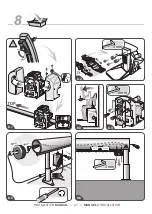
Page 29: ...X 1 17 3 mm 6 mm 3 mm 8 8 1 8 5 8 3 8 6 8 4 8 2 INSTALLATION MANUAL 27 MANUEL D INSTALLATION...
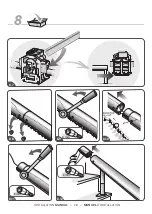
Page 31: ...A B 7 mm 8 8 15 8 16 8 14 8 13 INSTALLATION MANUAL 29 MANUEL D INSTALLATION...
Page 34: ...A B 5Nm M6 900 4mm 4mm 44 Lb In A A 6 A 5 A 8 A 7 INSTALLATION MANUAL 32 MANUEL D INSTALLATION...
Page 51: ......

