background image

Adjustments options 


24 

 Version 2015v1 


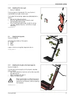
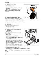
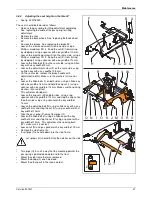
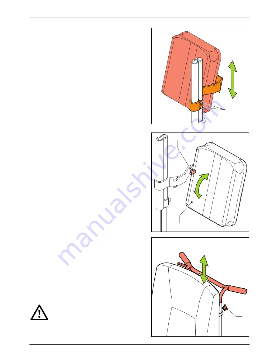
2.11.1  Adjusting the height of the calf pad 


See fig. 010512010. 

 
The calf pad can be adjusted in height as follows: 


Loosen Allen screw (A) a few turns with an Allen key with a 
key width of 4 mm. 


Slide the calf pad up to the desired height. 


Tighten the Allen screw again. 

 
XXXXXX-010512010.en.doc 


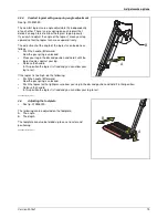
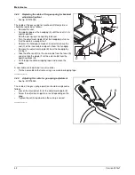
2.11.2  Adjusting the angle of the calf pad 


See fig. 010512020. 

 
The angle of the calf pad can be adjusted as follows: 


Loosen nut (A) a few turns with a spanner with a key width 
of 13 mm. 


Place the calf pad (B) in the desired position. 


Tighten the nut again. 

 
XXXXXX-010512020.en.doc 


2.12 

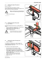
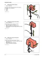
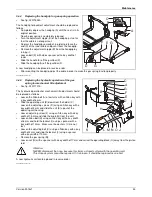
Adjusting the height of the push bracket 


See fig. 010517010. 

 
The push bracket can be adjusted in height, so that the 
assistant can push the wheelchair in a position that is as 
comfortable as possible. 
 
The push bracket can be adjusted in height as follows: 


Loosen both winged screws (A). 


Slide the push bracket up or down to the desired height. 


Tighten both winged nuts tightly, so that the push bracket 
cannot slip. 


Attention: 


The cable for the tilt-adjustment option may not be 
stretched too taut. 


SADKIB-010517010-nl.doc 


A


A

B

A

Summary of Contents for IBIS-2

Page 1: ...SERVICE MANUAL IBIS 2...

Page 2: ...e right to changes and modifications The information provided is valid for the product in its standard version Handicare cannot be held liable for possible damage resulting from specifications of the...

Page 3: ...pad option 23 2 12 Adjusting the height of the push bracket 24 3 Maintenance 25 3 1 Maintenance table 25 3 2 Back wheels 12 25 3 3 Back wheels 24 27 3 4 Swivel castors 29 3 5 Gas springs 30 3 6 Cables...

Page 4: ...Contents 4 Version 2015v1 021 Armrest 68 022 Seat backrest calf pad 69 023 Headrest 72...

Page 5: ...o see to it that work is always done safely particularly with respect to activities where the wheelchair must be lifted up We advise that you contact our service department before doing repair work on...

Page 6: ...roduct has the following decals and labels See fig 010004010 24 B C A E D F 12 A Tilt adjustment mechanical B Set tilt adjustment C Gas spring adjustment backrest option D Brake bracket E Tire pressur...

Page 7: ...ake on To use the brake bracket see Parking PICPRO 010004350 en doc E Tire pressure back wheels 12 For the right tire pressure see Product specifications PICPRO 010004370 en doc F Tire pressure back w...

Page 8: ...e Identification of the product XXXXXX 010006000 nl doc Identification plate See fig 010007000 On this plate A information on the product can be found See Identification of the product SADKIB 01000700...

Page 9: ...e Netherlands Notwithstanding the rights and obligations of Handicare Client and User set forth in Handicare s general terms and conditions of sale the rights of the Client and or User towards Handica...

Page 10: ...lt in the Product 2 Handicare accepts no other or further liability than delineated under 1 In particular Handicare accepts no liability for consequential damage in any form whatsoever XXXXXX 01000802...

Page 11: ...technical specifications may not be changed 1 3 Modifications Modification of parts of this product is not permitted 1 4 Safety To avoid accidents and undesirable situations it is of great importance...

Page 12: ...ssure distribution 2 The range of body functions The body is supported in such a way that you can carry out a wide variety of actions because you can move into a stable sitting position A specialist o...

Page 13: ...ng the seat depth See fig 010502020 The seat depth can be adjusted between approximately 44 cm and 52 cm 17 and 20 by shifting the backrest The seat depth adjustment should be done as follows Loosen t...

Page 14: ...ce securely XXXXXX 010502050 en doc 2 2 3 Adjusting the seat width See fig 010502030 The space between the two armrests can be adjusted as desired between 36 cm and 52 cm 15 and 20 The holder for the...

Page 15: ...ith a spanner with a key width of 13 mm Adjust the new angle by turning the bolts B in or out some more Turning them out will increase the seat angle Turning them in will decrease the seat angle Tight...

Page 16: ...ghten the clamp tightly so that the footplate cannot slip Make sure that there is sufficient free space underneath the footplate to operate the wheelchair over obstacles without the footplate becoming...

Page 17: ...5030 nl doc 2 5 Adjusting the legrests See fig 010504000 Adjustment possibilities of the legrests A Length B Width C Depth Legrests also have an optional angle adjustment XXXXXXX 010504000 en doc 2 5...

Page 18: ...per legs the legrests can be adjusted in terms of depth The adjustment of the depth of the legrests should be done as follows Loosen the Allen bolt A a few turns with an Allen key with a key width of...

Page 19: ...ace your leg in the desired position and hold it until the legrest comes against your leg Release the handle In this position the legrest is fixed and you can allow your leg to rest If the legrest is...

Page 20: ...left and right footplate should be exchanged The exchanging of the footplates should be done as follows Remove the calf strap See Removing calf strap Loosen the set bolt A a few turns with an Allen k...

Page 21: ...desired position Tighten the Allen bolts again Note that the adjustment is carried out equally on the left and the right side SADKIB 010508020 nl doc 2 8 Adjusting the height of the side panel See fi...

Page 22: ...ght adjustment can be done as follows Loosen the wing nut A a few turns Slide the headrest B to the desired height Securely tighten the wing nut again so that the headrest cannot shift XXXXXX 01051001...

Page 23: ...ecurely again XXXXXX 010510030 en doc 2 10 Adjusting the calf strap See fig 010511000 The calf strap A serves to support the calves and is attached to the legrests The calf strap can be removed to mak...

Page 24: ...rns with a spanner with a key width of 13 mm Place the calf pad B in the desired position Tighten the nut again XXXXXX 010512020 en doc 2 12 Adjusting the height of the push bracket See fig 010517010...

Page 25: ...nings and bolts tighten if necessary X Checking and cleaning of the brakes X It is recommended to have your wheelchair serviced by your dealer at least once a year or in case of intensive use once eve...

Page 26: ...ata Remove the support from the wheelchair The wheelchair is ready to drive again SADKIB 010705010 nl doc 3 2 2 Replacing tire of back wheel 12 When replacing a tire of a back wheel the wheel should b...

Page 27: ...the correct pressure Soft tires yield less optimal driving for the wheelchair It also costs more energy to move the wheelchair forward Moreover tire wear when driving on soft tires is unnecessarily g...

Page 28: ...Remove the back wheel to be repaired from the wheelchair See Removing the back wheels Twist off the valve to let the air out of the tire completely Using tire levers pull one side of the tire across...

Page 29: ...To replace the rim of the back wheel see repairing the tire of the back wheel 24 replacing tire of back wheel 24 replacing the back wheel 24 SADKIB 020713010 nl doc 3 4 Swivel castors For the proper f...

Page 30: ...20714010 The gas spring for mechanical tilt adjustment should be replaced as follows Remove the seat Completely depress the handgrip A until the seat is in its original position Now the gas spring is...

Page 31: ...les for gas spring operation The Ibis may be equipped with gas springs for Tilt adjustment mechanical Backrest adjustment option SADKIB 020714000 nl doc 3 6 1 Replacing the cable of the gas spring for...

Page 32: ...handgrip Remove the adjustment nipple B from the handgrip by turning it Take the other end D of the inner cable from the lever E and also take the nipple F of the outer cable from the operating block...

Page 33: ...ion for mechanical tilt adjustment should be replaced as follows Loosen the Allen bolt A a few turns with an Allen key with a key width of 6 mm Slide the operating unit B down from the holder C Loosen...

Page 34: ...o release plate G Remove the brake plate H Attention Make sure that the spacing washers are not lost The locknuts may not be used again use new ones when replacing A new brake plate can be placed in r...

Page 35: ...e looser Tighten the nut A again SADKIB 020716010 nl doc 3 7 4 Adjusting the brake 24 See fig 020716020 The brakes for hand or foot operation should be adjusted as follows Loosen nut A with a spanner...

Page 36: ...th of 13 mm and stop the cap nut on the other side using a ring spanner with a key width of 13 mm Loosen the nuts F on both sides using a spanner with a key width of 13 mm and remove the brake handle...

Page 37: ...on both sides using an Allen key with a key width of 6 mm and hold the cap nut J using a spanner with a key width of 13 mm Make sure the spacing washers K are not lost This will release bridge L Loos...

Page 38: ...easily with a dry soft cloth Removing mud and or other wet dirt Parts that are soiled with wet dirt can best be cleaned by first wiping the dirty parts with a wet sponge and then wiping them dry with...

Page 39: ...10 Static stability upward 11 Static stability sideways 15 Tilt adjustment mechanical 3 28 Seat angle 1 6 Effective sitting depth adjustable 440 mm 520 mm Effective sitting width adjustable 380 mm 525...

Page 40: ...ffective sitting width adjustable 380 mm 525 mm B Total width 630 mm 720 mm C Effective sitting depth adjustable 440 mm 520 mm D Total length including legrest 920 mm 1200 mm E Sitting height from the...

Page 41: ...ment mechanical 3 28 Seat angle 1 6 Effective sitting depth adjustable 440 mm 520 mm Effective sitting width adjustable 380 mm 505 mm Sitting height from the front 500 mm 600 mm Back angle 83 120 Back...

Page 42: ...he front 500 mm 600 mm F Back height 520 mm 570 mm G Lower leg length 390 mm 500 mm SADKIB 010901020 nl doc 4 2 Approval The products meet EN 12183 1 Requirements and testing methods for static impact...

Page 43: ...ions Version 2015v1 43 4 3 Authorized service and technical support For problems or questions contact your dealer Ask us for information on the nearest dealer Manufacturer Handicare Supplier stamp XXX...

Page 44: ...t be bought separately The relevant part is part of the composition that is shown Only the composition can be ordered so it must be replaced in its entirety Boxed position numbers refer to the relevan...

Page 45: ...rrier incl wheels 12 010 Carrier incl wheels 24 011 Sedeo seatframe 012 Spring mechanical backrest adjustment 013 Gas spring backrest adjustment 014 Hydraulic mechanical operation tilting adjustment 0...

Page 46: ...Threaded end VZ M12 X 622 12 02010 5610 2 Torsion springs 13 00000 2003 4 Washer flat M8 D125A vz 14 00000 1802 8 Nut M8xP1 25 15 00000 5924 1 Threaded end VZ M8 X 488 16 02010 5020 1 Side frame righ...

Page 47: ...002 Swivel castors Pos Article number Units Description 1 9002161 2 Front fork 2004 02010 5910 2 Front fork and axle 2004 2 1001447 2 Wheel PU complete 2004 170 00171 000 2 Wheel PU complete 2004 028...

Page 48: ...cle number Units Description 1 1001138 2 Rear wheel air complete 2004 01010 3280 2 Rear wheel air complete 1001166 2 Rear wheel PU complete 2 01010 3400 2 Tire 12 3 01010 3300 2 Inner tube 12 4 01010...

Page 49: ...0 00031 000 2 Rear wheel 24 air complete 170 00361 000 2 Rear wheel 24 PU complete 2 02450 2100 2 Tire 24 3 02450 2000 2 Inner tube 24 4 02450 2200 2 Rim 5 02450 3682 2 Hoop 6 00001 1465 2 Sticker tir...

Page 50: ...0 3703 2 Buttonhead M6X16 vz 9 02443 0412 2 Adjustment block 10 00000 4018 2 Cyl cap screw inn zk M6X405 VZ 11 00000 2002 4 Washer flat M6 D125A VZ 12 02010 1312 2 Bush 13 00000 3722 2 Screw BCK KR VZ...

Page 51: ...rake arm 9 00000 3709 2 Buttonhead M6X30 VZ 10 108 00011 000 1 Brake hub left 108 00001 000 1 Brake hub right 11 00000 1701 8 Locknut M6 D985 8 VZ 12 00000 2002 6 Washer flat M6 D125A VZ 13 00000 1710...

Page 52: ...24 02010 3111 1 Brake handle left 02010 3211 1 Brake handle right 25 00000 2310 6 Flat washer M10 PA 26 02010 3310 1 Connecting shaft 27 00000 4903 2 Ball knob brake handle M8 R 32 ZW 28 00000 4024 2...

Page 53: ...1 0304 2 Dowel pin 5 03447 3212 1 Handle 6 03447 3412 2 Strip 7 03447 3812 1 Bush 8 03447 3110 1 Housing part left 9 03447 3010 1 Housing part right 10 00000 4061 2 Cil cap screw inn zk M4X12 VZ 11 00...

Page 54: ...612 1 Plate 2 00000 4004 1 Cil cap screw inn zk M6X45 VZ 3 00000 4009 2 Allen bolt M8x35 4 02447 0223 2 Washer 5 02447 0123 1 Spacing block 6 00000 3728 1 Buttonhead M8X12 ISO7380 7 00000 9206 1 Inser...

Page 55: ...knut M12 D985 8 vz 3 00000 2005 6 Washer flat M12 D125A vz 4 00000 4121 2 Hex Bolt M12X70 D931 8 8 VZ 5 00000 6007 4 Shim 12 WHEEL IBIS 12 18 1 D988 6 00000 2205 2 Spring washer M12 D127B VZ 7 00000 1...

Page 56: ...2 Insert cap round 28 BLACK 2 00000 1704 2 Locknut M12 D985 8 vz 3 00000 2005 6 Washer flat M12 D125A vz 4 00000 4121 2 Hex Bolt M12X70 D931 8 8 VZ 5 175 00011 000 2 Quick release axle 6 00000 1608 4...

Page 57: ...nded right 9 02040 0623 1 Strip 10 02040 0523 1 Receiving frame 11 05020 0423 1 Sedeo seating frame 12 00000 3722 4 Screw BCK KR VZ M6X50 13 9000673 2 Pressure plate Sedeo 14 02030 4023 2 Back part 1...

Page 58: ...mechanical backrest adjustment Pos Article number Units Description No longer available as on drawing Has been replaced for new type as on Ibis X Series and Yes Series See pos 1 for article number 1...

Page 59: ...ticle number Units Description 1 02152 9200 1 Gas spring adjustment 2 1007008 1 Handle 3 02010 6910 1 Gas spring operating mechanism 4 181 00011 010 1 Cable 5 1002813 1 Gas spring 6 00000 1602 1 Hex N...

Page 60: ...9 1002809 1 Gas spring 400N 1002810 1 Gas spring 600N 10 00000 1701 1 Locknut M6 D985 8 VZ 11 00000 2002 1 Washer flat M6 D125A VZ 12 00001 0106 1 Screw 13 02010 7810 1 Clamping block 14 02010 6712 1...

Page 61: ...ription 1 00000 3709 4 Buttonhead M6X30 VZ 2 00000 2202 4 Spring washer M6 D127B VZ 3 02010 6182 2 Upper block 4 02010 7682 2 Washer 5 00000 3709 2 Buttonhead M6X30 VZ 6 00000 7501 2 Stauff block ALU...

Page 62: ...2 Washer flat M6 D125A VZ 10 00000 5002 4 Bearing bush Nylon 08X11X13 11 01050 0211 1 Upper pipe 12 01050 0812 1 Pin 13 01050 1311 1 Lower pipe 14 00000 9302 2 Insert cap 15 00000 4100 1 Hex Bolt M8X1...

Page 63: ...2 02030 0111 1 Handlebars 3 00000 6801 2 Star knob outs M8X30 BLACK MH 4 1001834 1 Back frame 5 01502 1223 1 Insert tube left 6 00000 3501 2 Adjusting screw BZK M8X10 D913 VZ 7 05245 0723 1 Middle par...

Page 64: ...Parts lists 64 Version 2015v1 018 Footplate with hinge 1 Pos Article number Units Description 1 See page 67...

Page 65: ...r part right 3 01500 1112 2 Legrest release lever 4 01500 2212 2 Legrest release spring 5 1 Footplate left See page 67 1 Footplate right See page 67 6 01263 9000 1 Calf strap 7 1004189 2 Calf plate hi...

Page 66: ...elease lever 5 01500 2212 2 Legrest release spring 6 00000 3706 2 Button head M8X25 7 00000 1802 2 Cap lock nut M8 8 1008076 1 Gas spring with gas spring control left 1008077 1 Gas spring with gas spr...

Page 67: ...3607 15 140 00351 000 140 00321 000 1003608 17 01500 9219 01500 9319 140 00021 000 19 140 00361 000 140 00331 000 1003609 21 1003601 1003598 1003610 23 1003602 1003599 1003611 25 1003603 1003600 10036...

Page 68: ...ion 1 221 00111 505 2 Armrest 40 cm 2 02040 0311 2 Upper part long 3 00000 3206 4 Screw bck kr M5X16 D7985 4 00000 3541 2 Adjusting screw crater M8X10 D916 5 9002127 2 Center piece 6 02040 0782 2 Brac...

Page 69: ...edeo Seat See page 70 2 00000 3617 2 Screw M5X30 3 00000 6501 2 Pipe clamp DIA 22 black 4 220 00121 505 1 Calf plate standard 220 00141 505 1 Calf plate small 5 00000 3206 4 Screw M5X16 6 1 Sedeo back...

Page 70: ...4 1002028 50x58 1002029 54x50 1002030 54x54 1002031 54x58 1002032 BOARD BOARD WITH REAR PAN PAN W X D 42x50 1002042 1002054 202 41141 505 46x50 1002045 1002057 202 41221 505 50x50 1002048 1002060 202...

Page 71: ...x56 1002152 1002170 1002188 1002197 42x60 1002153 1002171 1002189 1002198 46x56 1002154 1002172 1002190 1002199 46x60 1002155 1002173 1002191 1002200 50x56 1002156 1002174 1002192 1002201 50x60 100215...

Page 72: ...505 1 Headrest Type 2 Large black Sellaskin 2 00000 3206 8 Screw bck kr M5X16 D7985 3 02193 0023 1 Metal Section Headrest Standard Adjustable 02194 0023 1 Metal Section Headrest With Adjustable Width...

Page 73: ...icle number 01010 3580 into 01010 3280 59 013 2 Changed article number 152 00181 000 into 1007008 66 020 10 Changed article number 906 00000 031 into 1004189 66 020 10 Changed article number 906 00311...

Page 74: ......

Reviews: