Maintenance
Version 2015v1
37
3.8.2
Adjusting the seat height on the Ibis 24”
•
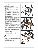
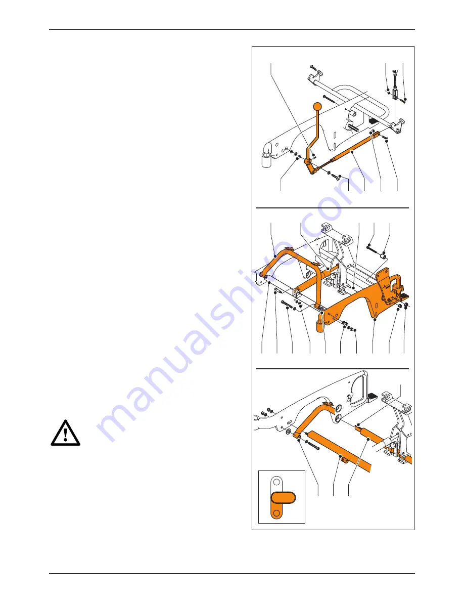
See fig. 020718020.
The seat should be lowered as follows:
•
Release the gas spring for tilting adjustment completely.
See ‘replacing the cable of the gas spring for tilting
adjustment’.
•
Remove the seat.
•
Remove the back wheels. See 'replacing the back wheel
24” ‘.
•
Remove the brakes. See 'replacing the brake 24” ‘.
•
Loosen the crosshead screw (A) on one side, using a
Phillips screwdriver PH -2. Keep the nut (B) from turning
by stopping it using a spanner with a key width of 10 mm.
•
Loosen the crosshead screw (A) on the same side, using a
Phillips screwdriver PH -2. Keep the nut (D) from turning
by stopping it using a spanner with a key width of 10 mm.
•
Loosen the Allen bolt (E) on the same side, using an Allen
key with a key width of 3 mm.
•
Loosen the adjustment screw (F) on the same side, using
an Allen key with a key width of 2.5 mm.
•
On the same side, remove the brake handle with
adjustment rod (G). Make sure the washers (H) are not
lost.
•
Loosen the Allen bolts (I) on both sides, using an Allen key
with a key width of 6 mm and hold the cap nut (J) using a
spanner with a key width of 13 mm. Make sure the spacing
washers (K) are not lost.
This will release bridge (L).
•
Loosen the cap nuts (M) on both sides, using a ring
spanner with a key width of 13 mm and stop the cap nut on
the other side using a ring spanner with a key width of
13 mm.
•
Loosen the adjusting bolt (N) using an Allen key with a key
width of 4 mm and stop the nut (O) using a spanner with a
key width of 10 mm.
•
Take the gas spring (P) away from pipe (Q).
•
Loosen the Allen bolt (V) using an Allen key with a key
width of 4 mm and stop the nut (X) using a spanner with a
key width of 10 mm. This will release the spacing bush
(W): make sure it is not lost.
•
Loosen nut (R) using a spanner with a key width of 19 mm.
•
Remove the side frame (S).
•
Insert pipe (T) one hole down into the side frame.
•
•
The leaf springs (U) should fall into the notches on the side
frame.
•
•
•
•
Turn pipe (Q) in such a way that the mounting point of the
gas spring is pointed downward and to the front.
•
Mount the side frame that was removed.
•
Mount the bridge (L) one hole down.
•
Mount the other parts in the reverse order.
1
2
T
Q
L
J M
S
R X
E
H
G
D
C
K
O
I
N
Q
U
T
P
L
V W
F
B
A


