background image

228  

HANDICARE SIMPLICITY MANUALE D’INSTALLAZIONE

Angolo delle scale

A

B

C

D

Angolo

37°

38°

39°

40°

41°

42°

43°

44°

45°

46°

47°

48°

49°

50°

Sbalzo guida orizzontale*

A

141

141

140

139

138

138

137

136

135

135

134

133

132

132

Instrusione guida piano terra

B

352

349

346

343

340

336

333

330

327

324

321

318

315

312

Dal naso superior

e alla terra

C

Estensione guida dal naso*

D

178

180

182

184

186

189

191

193

195

198

200

202

204

206

Lunghezza taglio guida (C+D)

E

Angolo

45°

A

135

B

327

C

3250

D

195

E

3445

*Dati minimi – quando l’intrusione superior

e è critica. 

Esempio

Modello Simplicity – dettagli sulla guida

Appendice 5

Summary of Contents for SIMPLICITY

Page 1: ...MANISSSIMML INSTALLATION MANUAL INSTALLATIEHANDLEIDING INSTALLATIONSANLEITUNG MANUEL D INSTALLATION MANUAL DE INSTALACI N MANUALE DI INSTALLAZIONE SIMPLICITY...

Page 2: ...rack section Top track section e g a left hand lift comprises 2 purple and 4 black boxes a right hand lift comprises 2 green and 4 black boxes 2 Installation tools required Note The installation engin...

Page 3: ...ner 8 x bolts Hacksaw 4 x grub screws Tin snips Final limit stops x 1 End stops x 1 Mounting feet x 3 Top track section x 1 Bottom track section x 1 1 Position the bottom section of the track 2m on th...

Page 4: ...rrect orientation The splice bar has three flat faces and one sloping face The sloping face MUST be positioned against the sloping face on the extrusion Figure 3 3 If the track is less than 2000mm and...

Page 5: ...m e centre top c right bottom f right top Repeat this process until the bolts are all secure torque setting 8 9Nm 7 Push the plastic carrier strip down from the top track section to meet the plastic c...

Page 6: ...taircase with open bannisters on the bannister side they must be covered with a solid sheet material for safety 12 If the power supply is a At the top of the track Feed the long power cable with the p...

Page 7: ...igure 14 ensuring that the power supply cable is fed through the channel provided so that it exits the track on the WALL side 18 Tighten the grub screws to secure the end cap to the track Note The gru...

Page 8: ...13mm Spanner 13mm Socket 1 Slide the track to the side of the stairs that it will be finally located to position the feet The feet should be positioned so that they are touching the stringer Figure 15...

Page 9: ...the track for a single section track to allow clearance when the Slide Track moves Figure 17 The track should be approximately 25mm from the nose of the stairs 5 Position the remaining feet on the st...

Page 10: ...pack onto the track until the drive pinion meets the beginning of the rack Figure 24 9 Turn the power pack on from the main switch on the lower safety edge Figure 25 10 Using the loading driving links...

Page 11: ...HANDICARE SIMPLICITY INSTALLATION MANUAL 11 ENGLISH Figure 24 Figure 25 Figure 27 Figure 28 Figure 26 Figure 23 Loading the power pack...

Page 12: ...n Once loaded this dipswitch should be returned to the ON position to enable the Slide Track see wiring diagrams Note Do not drive the power pack in the UP direction until the top end cap has been fit...

Page 13: ...e 2 Position the top hat on to the power pack Figure 32 3 Insert the one bolt through the stair side slotted hole in the footplate chassis and then position the spacer supplied Figure 33 ensuring that...

Page 14: ...is to level it Figure 35 8 Fully tighten the two footplate bolts 9 Tighten the safety bolt until it just bites on to the power pack chassis Note Over tightening the safety bolt will twist the footplat...

Page 15: ...ers to the seat bolts Figure 39 4 Bolt the seat post to the power pack Figure 40 Note If you fit the seat post to the power pack in the configuration that it is delivered the seat to footplate height...

Page 16: ...ocates 9 Fully swivel the seat using the swivel levers 10 Re fit the seat base bolt and washer that you removed in step 6 Figure 44 11 Swivel the seat back to the drive position using the swivel lever...

Page 17: ...HANDICARE SIMPLICITY INSTALLATION MANUAL 17 ENGLISH Figure 44 Figure 45 Figure 46 Fitting the seat...

Page 18: ...stairs to ensure that it will not encounter any unforeseen obstacles Figures 47 and 48 Note Look for any other potential obstacles such as window ledges or exposed pipework that could obstruct the mov...

Page 19: ...y the bottom stop may slide all the way down the track f Slide the bottom stop down the track so that the distance from the top edge of the stop to the inside face of the end cap is the same as the di...

Page 20: ...e the bottom safety edge by undoing the two visible cross head screws on the top edge and the one hidden Allen by the track Figure 53 3 Slide the bottom safety edge down the track to expose the contro...

Page 21: ...ion see Figure 56 iii Press and hold the red button on the PCB Figure 54 a yellow LED will illuminate on the PCB iv Press any button on one handset and the yellow light will go out v Programming is co...

Page 22: ...te the lift should stop c Drive the lift in the down direction d Press the downstairs edge of the footplate the lift should stop e Drive the unit in the down direction f Press the underside of the foo...

Page 23: ...end of the track before the Slide Track has completed its travel then the stairlift will stop and the Slide Track will continue to the end of its travel 2 Sit on the stairlift a Drive the lift to the...

Page 24: ...stairlift for a prolonged period such as a holiday Seat belt The seat belt should be used every time the stairlift is used Operating lever Which way is up which way is down How the toggle can be used...

Page 25: ...imum carrying capacity is 140kg 22 stone 308lb The stairlift is designed for carrying people only NEVER allow children to play on or with the stairlift NEVER allow water to come into contact with the...

Page 26: ...etaining bolt Figure 64 b Apply the lubricant to the nylon washer c Refit the seat and refit the retaining bolt Figure 64 3 Check all of the safety features on the lift as described in the Testing sec...

Page 27: ...tify Symptom Lift shuts down when loaded on to track Cause Short on comms brush to track Solution Use insulated brush loading tool Symptom Power swivel will not operate Cause Incorrect top limit reed...

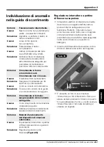
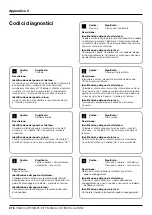
Page 28: ...Final limit activated Description Keyswitch seat swivel OSG or overrun activated Telephone fault finding action Ask client to ensure keyswitch is on and seat is fully swivelled to drive position If t...

Page 29: ...er On site fault finding action Drive lift to charge contacts Check charging circuit if Okay code not displayed If lift will not drive replace batteries and check charging circuit Code Meaning 8 8 Up...

Page 30: ...g action Replace main board Code Meaning n Half speed Description Telephone fault finding action Send engineer if permanently showing On site fault finding action Check reed switches and dipswitch set...

Page 31: ...d has a software fault Telephone fault finding action Send engineer On site fault finding action Replace main board Code Meaning N A Over current Description N A Telephone fault finding action Send en...

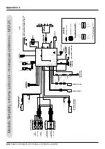
Page 32: ...IR 1 GREEN DOWN DIRECTION BLUE TOGGLE COMMON ORANGE UP DIRECTION BROWN CHASSIS TOP SAFE EDGE GREY SAFE EDGE COMMON VIOLET VIOLET VIOLET VIOLET VIOLET 4 5 6 3 2 1 3 2 1 2 1 2 1 2 1 2 1 2 1 2 1 4 5 6 2...

Page 33: ...IR 1 GREEN DOWN DIRECTION BLUE TOGGLE COMMON ORANGE UP DIRECTION BROWN CHASSIS TOP SAFE EDGE GREY SAFE EDGE COMMON VIOLET VIOLET VIOLET VIOLET VIOLET 4 5 6 3 2 1 3 2 1 2 1 2 1 2 1 2 1 2 1 2 1 4 5 6 2...

Page 34: ...STOP SW4 GREEN BLUE ORANGE ORANGE GREEN SW2 SW6 SW7 SW8 SW3 SW5 DIRECTION LH UP RH DN SWITCH OPEN CIRCUIT FOOTPLATE DOWN SWITCH CLOSED CIRCUIT FOOTPLATE UP ARM INTERLOCK 1 24V FINAL LIMIT ESTOP DETECT...

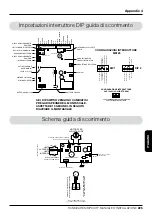
Page 35: ...plicity DIP Settings MS125 board for Left and Right Hand Slide Track FRONT PANEL LED CONNECTION SLIDETRACK SCHEMATIC LH RH CSE126EL SLIDETRACK CONTROLLER PCB SLIDE TRACK MOTOR JUMPER MUST BE PRESENT O...

Page 36: ...e to floor mm minus B track reduction from nose equals C cut track length Example D imension A 3250mm Angle 45 3250 74 3176 Final cut track length 3176mm Angle 37 38 39 40 41 42 43 44 45 46 47 48 49 5...

Page 37: ...42 43 44 45 46 47 48 49 50 First Riser Max Height mm for zero bottom intrusion D 162 164 166 168 169 171 172 173 173 174 174 173 173 172 Top Overhang mm at given staircase angle E 213 211 209 207 205...

Page 38: ...132 132 Ground Track Intrusion B 352 349 346 343 340 336 333 330 327 324 321 318 315 312 Top Nose to Ground C Track Extension from Nose D 178 180 182 184 186 189 191 193 195 198 200 202 204 206 Track...

Page 39: ...HANDICARE SIMPLICITY INSTALLATION MANUAL 39 ENGLISH Notes...

Page 40: ...tuk Voor een links geplaatste lift hebt u bijvoorbeeld 2 paarse en 4 zwarte dozen nodig terwijl voor een rechts geplaatste lift 2 groene en 4 zwarte dozen nodig zijn 2 Benodigd installatiegereedschap...

Page 41: ...2 inbusschroeven voor de bovenste verbindingsstaaf en de 4 bouten voor de onderste verbindingsstaven deze vindt u in de rode zak met montageonderdelen Benodigde onderdelen Montageset 3 x koppelingssta...

Page 42: ...ppelingsstaaf heeft drie platte kanten en n schuine kant De schuine kant MOET tegen de schuine kant van het profiel worden geplaatst Figuur 3 3 Als de rail korter is dan 2000mm en de rail moet ter ple...

Page 43: ...aar Figuur 8 De bouten moeten in de volgende volgorde worden aangedraaid a linksonder d linksboven b middenonder e middenboven c rechtsonder f rechtsboven Herhaal deze procedure totdat alle bouten ste...

Page 44: ...de stappen niet over de trap kan verschuiven NB Als de traplift op een trap met open trapspijlen wordt gemonteerd moeten de spijlen uit veiligheidsoverwegingen worden afgedekt met stevig plaatmateriaa...

Page 45: ...nteerd Als dit niet correct gebeurt kan de lift beschadigd raken 17 Monteer de onderste eindkap op de rail Figuur 14 Zorg ervoor dat de voedingskabel zodanig door het kanaal loopt dat deze aan de zijd...

Page 46: ...opsleutel Figuur 16 Figuur 15 1 Schuif de rail naar de kant van de trap waar de rail uiteindelijk wordt geplaatst om de steunen te plaatsen De steunen moeten zodanig worden geplaatst dat ze de trapboo...

Page 47: ...de beweging van de schuifrail Figuur 17 De rail moet zich op ongeveer 25mm afstand van de trapneus bevinden 5 Plaats de overige steunen op de treden en bevestig ze losjes op de trap De laatste steun...

Page 48: ...el raakt Figuur 24 9 Schakel de unit in via de hoofdschakelaar op de onderste veiligheidsrand Figuur 25 10 Voer de unit over de rail met behulp van de aandrijfstekkers of de bedieningshendel Figuur 26...

Page 49: ...INSTALLATIEHANDLEIDING HANDICARE SIMPLICITY 49 NEDERLANDS De unit plaatsen Figuur 24 Figuur 25 Figuur 27 Figuur 28 Figuur 26 Figuur 23...

Page 50: ...schuifrail 14 Let er tijdens het plaatsen van de unit op dat de twee stroomrailhulpstukken juist zijn geplaatst Figuur 29 15 Dip schakelaar 2 van de hoofdprintplaat moet op OFF staan om de unit te ku...

Page 51: ...abel kunt monteren 2 Plaats de afstandsbus op de unit Figuur 32 3 Steek n bout door het sleufgat in het voetensteunframe aan de trapkant en bevestig vervolgens de bijgeleverde afstandsring Figuur 33 Z...

Page 52: ...e stellen Figuur 35 8 Draai de twee bouten van de voetenplank stevig vast 9 Draai de borgbout aan totdat deze net het frame van de unit raakt NB Als u de borgbout te ver vastdraait kan het voetensteun...

Page 53: ...iguur 39 4 Bevestig de zittingkolom met bouten op de unit Figuur 40 NB Als u de zittingkolom in de geleverde configuratie op de unit monteert bedraagt de afstand van de zitting tot de voetenplank 390m...

Page 54: ...p van de draaihendels helemaal rond 10 Draai de bout en ring die u in stap 6 hebt verwijderd weer vast Figuur 44 11 Draai de zitting met behulp van de draaihendels weer terug in de bewegingsstand 12 V...

Page 55: ...INSTALLATIEHANDLEIDING HANDICARE SIMPLICITY 55 NEDERLANDS De zitting monteren Figuur 44 Figuur 45 Figuur 46...

Page 56: ...omhoog en omlaag om te controleren of er geen onvoorziene obstakels zijn Figuur 47 en 48 Figuur 47 Figuur 48 Figuur 49 Figuur 50 Figuur 51 Benodigde onderdelen Installatie kit Groen zakje Houtschroev...

Page 57: ...stop met de schuine kant zo ver los dat u hem net kunt verschuiven NB Let op dat u de schroeven niet volledig losdraait anders kan de onderste eindstop helemaal langs de rail naar beneden schuiven f S...

Page 58: ...werkhoogte bevindt 2 Verwijder de onderste veiligheidsrand Draai hiervoor de twee zichtbare kruiskopschroeven aan de bovenste rand los en verwijder de inbusbout die achter de rail zit verborgen Figuu...

Page 59: ...deze knop ingedrukt totdat op de printplaat een gele led gaat branden iv Druk op een willekeurige toets op een handset om het gele lampje uit te schakelen v Het programmeren is voltooid 5 Voer een te...

Page 60: ...steunframe Figuur 61 a Beweeg de lift omhoog b Druk op de bovenste veiligheidrand van de voetenplank de lift moet nu tot stilstand komen c Beweeg de lift omlaag d Druk op de onderste veiligheidsrand v...

Page 61: ...normale snelheid Als de lift wel het einde van de rail heeft bereikt als de schuifrail volledig is in of uitgeschoven stopt de traplift en schuift de schuifrail verder tot deze de eindstand bereikt 2...

Page 62: ...rbeeld een vakantie niet gaat gebruiken Veiligheidsgordel De veiligheidsgordel moet tijdens het gebruik van de traplift altijd worden gedragen Bedieningshendel Welke kant is omhoog en welke kant is om...

Page 63: ...iken Het maximale draagvermogen is 140 kg De traplift is uitsluitend bedoeld voor vervoer van mensen Laat NOOIT kinderen op of met de traplift spelen Laat de interne onderdelen van de traplift NOOIT i...

Page 64: ...lon ring c Plaats de zitting weer terug en draai de borgbout opnieuw vast Figuur 64 3 Controleer alle veiligheidsfuncties van de lift zoals beschreven in het hoofdstuk Testen van de installatiehandlei...

Page 65: ...De lift schakelt uit als deze op de rail wordt geplaatst Oorzaak Kortsluiting in spanningsvoerende koolborstel naar rail Oplossing Gebruik het hulpgereedschap om de koolborstel niet te beschadigen Sym...

Page 66: ...eindstop rechts Onderste eindstop links Omschrijving Eindbegrenzingen geactiveerd Foutopsporing per telefoon Vraag de klant op de unit beschermingen te kloppen voor het geval deze vastzitten Stuur ee...

Page 67: ...ng ter plaatse Plaats de lift op de oplaadpunten Als de code okay niet wordt weergegeven moet het oplaadcircuit worden gecontroleerd Vervang de accu s en controleer het oplaadcircuit als de lift niet...

Page 68: ...ng de hoofdprintplaat Code Betekenis n Halve snelheid Omschrijving Foutopsporing per telefoon Stuur een monteur als dit permanent wordt weergegeven Foutopsporing ter plaatse Controleer de reed contact...

Page 69: ...software versie 1 19 en hoger Omschrijving Voeding defect Foutopsporing per telefoon Stuur een monteur Foutopsporing ter plaatse Vervang de voeding Code Betekenis y Softwarefout Omschrijving De hoofd...

Page 70: ...N 3 CON 3 CON 2 CON 2 CON 2 CON 1 CON 1 CON 1 M1 DIAG IR 2 IR 1 GROEN OMLAAG BLAUW SPANNINGSVOERENDE BEDIENINGSHENDEL ORANJE OMHOOG BRUIN FRAME BOVENSTE VEILIGHEIDSRAND GRIJS SPANNINGSVOERENDE VEILIGH...

Page 71: ...1 PAARS PAARS GRIJS BRUIN LUS BRUIN LUS BRUIN BRUIN KABEL RAILVERBINDING ZIE LINKS GEPLAATSTE CIRCUIT BRUIN BRUIN BRUIN ROOD ROOD BRUIN KABEL RAILVERBINDING ZIE LINKS GEPLAATSTE CIRCUIT PAARS PAARS B...

Page 72: ...ROENE BLAUW ORANJE ORANGE GROENE SW2 SW6 SW7 SW8 SW3 SW5 DIRECTION LG OP RG NEER CIRCUIT SCHAKELAAR OPEN VOETENPLANK NAAR BENEDEN CIRCUIT SCHAKELAAR GESLOTEN VOETENPLANK NAAR BOVEN ARMLEUNING SCHAKELA...

Page 73: ...nd Right Hand Slide Track VOORPANEEL LED AANSLUITING MOTOR SCHUIFRAIL HULPDRAAD MOET AANWEZIG ZIJN OP DEZE TWEEWEGCONNECTOR ZWART CONTACT COMMUNICATIEKABEL RAIL NORMAAL GEOPENDE SCHAKELAARS GEBRUIKT V...

Page 74: ...te trede tot aan vloer min B reductie raillengte maakt C de lengte van de rail Voorbeeld M aat A 3250mm hoek 45 3250 74 3176mm Uiteindelijke raillengte 3176mm A C B Hoek 37 38 39 40 41 42 43 44 45 46...

Page 75: ...3 44 45 46 47 48 49 50 Eerste trede maximale hoogte mm Geen bovenuitloop D 162 164 166 168 169 171 172 173 173 174 174 173 173 172 Bovenuitloop mm voor de gegeven traphoeken E 213 211 209 207 205 202...

Page 76: ...41 140 139 138 138 137 136 135 135 134 133 132 132 Uitloop beneden B 352 349 346 343 340 336 333 330 327 324 321 318 315 312 Bovenste trede tot vloer C Bovenuitloop D 178 180 182 184 186 189 191 193 1...

Page 77: ...INSTALLATIEHANDLEIDING HANDICARE SIMPLICITY 77 NEDERLANDS Notes...

Page 78: ...r Lift besteht aus 2 violetten und 4 schwarzen Kartons ein rechter Lift besteht aus 2 gr nen und 4 schwarzen Kartons 2 Zur Installation erforderliche Werkzeuge Anmerkung Der Installationstechniker mus...

Page 79: ...terer Schienenabschnitt x 1 1 Den unteren Schienenabschnitt 2m mit den Verbindungsl chern nach oben weisend auf die Treppe legen Abb 1 Unabh ngig davon auf welcher Seite der Lift montiert wird muss si...

Page 80: ...erden Das Verbindungsst ck hat drei ebene und eine geneigte Fl che Die geneigte Fl che MUSS an der geneigten Fl che der Schiene anliegen Abb 3 3 Wenn die Schiene weniger als 2000mm lang ist und vor Or...

Page 81: ...nten links d oben links b unten Mitte e oben Mitte c unten rechts f oben rechts Wiederholen Sie den Prozess solange bis alle Schrauben fest angezogen sind Drehmomenteinstellung 8 9Nm 7 Das Plastik Tr...

Page 82: ...ss sie nicht mehr verrutschen k nnen Die F e hindern die Schiene daran die Treppe herunterzurutschen w hrend die n chsten Schritte durchgef hrt werden Anmerkung Wenn der Treppenlift in einem Treppenha...

Page 83: ...n oberen Kanal eingesetzt werden geschieht dies nicht so kann es zu Besch digungen des Lifts kommen 17 Die untere Endkappe auf die Schiene aufsetzen Abb 14 und dabei sicherstellen dass das Anschlusska...

Page 84: ...Schiene zur Positionierung der F e auf die Seite der Treppe schieben auf der sie montiert werden soll Die F e m ssen so positioniert werden dass sie die Treppenwange ber hren Abb 15 Anmerkung Wenn di...

Page 85: ...en sodass sich der Slide Track frei bewegen kann Abb 17 Die Schiene muss etwa 25mm von den Treppennasen entfernt sein 5 Die verbleibenden F e auf den Stufen positionieren und lose an der Treppe befest...

Page 86: ...Antriebsaggregat mit Hilfe der Lade Fahr Verbindung oder des Wechselschalters Abb 26 auf die Schiene fahren Das Antriebsaggregat muss auf eine Position etwa auf halber Strecke zwischen oberem und mitt...

Page 87: ...HANDICARE SIMPLICITY INSTALLATIONSANLEITUNG 87 DEUTSCH Abb 24 Abb 25 Abb 27 Abb 28 Abb 26 Abb 23 Einsetzen des Antriebsaggregats...

Page 88: ...s Antriebsaggregats muss sich DIP Schalter 2 auf der Hauptplatine in Position AUS befinden Nach erfolgtem Aufsetzen muss der Schalter wieder in die Position EIN gebracht werden um den Slide Track zu a...

Page 89: ...ggregat aufsetzen Abb 32 3 Eine Schraube durch das treppenseitige Langloch im Fu auflage Chassis schieben und dann die mitgelieferte Distanzscheibe auf diese aufschieben Abb 33 Sicherstellen dass die...

Page 90: ...8 Die beiden Fu auflage Schrauben fest anziehen 9 Die Sicherheitsschraube soweit anziehen bis sie gerade am Chassis des Antriebsaggregates bei t Anmerkung Zu starkes Anziehen der Sicherheitsschraube f...

Page 91: ...zpfosten in der angelieferten Konfiguration ans Antriebsaggregat geschraubt wird betr gt der Abstand zwischen Sitz und Fu auflage 390mm Der Sitzpfosten kann durch Verschieben der u eren H lse verl nge...

Page 92: ...erriegelung einrastet 9 Den Sitz ganz mit Hilfe der Drehhebel verdrehen 10 Sitzbasis Schraube und Vorsteckscheibe wieder einsetzen die in Schritt 6 entfernt wurden Abb 44 11 Sitz mit Hilfe der Drehheb...

Page 93: ...HANDICARE SIMPLICITY INSTALLATIONSANLEITUNG 93 DEUTSCH Abb 44 Abb 45 Abb 46 Montage des Sitzes...

Page 94: ...sicherzustellen dass es nirgendwo anst t Abb 47 und 48 Anmerkung Alle m glichen Hindernisse wie Fensterb nke oder freiliegende Verrohrung die die Bewegung des Lifts in diesem Stadium behindern k nnte...

Page 95: ...vorgehen der untere Endstop kann die Schiene ganz hinunterrutschen f Den unteren Stop soweit die Schiene hinunter schieben bis der Abstand von der Oberkante des Stops zur Innenseite der Endkappe dem...

Page 96: ...Herausdrehen der beiden sichtbaren Kreuzschlitzschrauben an der Oberkante und der verdeckten Inbusschraube nahe der Schiene entfernen Abb 53 3 Die untere Sicherheitskante in Richtung Schiene nach unt...

Page 97: ...dr cken und halten Abb 54 eine gelbe LED wird auf der Platine aufleuchten iv Auf einer Fernbedienung einen beliebigen Knopf dr cken und die gelbe LED erlischt v Das Programmieren ist abgeschlossen 5 b...

Page 98: ...cken der Lift muss stoppen c Den Lift die Treppe herunter verfahren d Die die Treppe hinunterweisende Kante der Fu auflage dr cken der Lift muss stoppen e Das Ger t die Treppe herunter verfahren f Di...

Page 99: ...Ende der Schiene erreicht bevor der Slide Track seine Bewegung beendet hat dann h lt der Lift an und der Slide Track f hrt weiter bis die Bewegung beendet ist 2 Setzen Sie sich auf den Treppenlift a...

Page 100: ...Sitzgurt Der Sitzgurt muss jedes Mal wenn der Treppenlift benutzt wird angelegt werden Bedienhebel In welche Richtung ist Auf in welche Richtung ist Ab Wie der Hebel bedient werden kann d h mit den F...

Page 101: ...40kg Der Treppenlift wurde ausschlie lich zum Personentransport gestaltet NIE Kinder auf oder mit dem Treppenlift spielen lassen Lassen Sie Komponenten des Treppenlifts NIE nass werden Wenn Sie Fl ssi...

Page 102: ...heibe aufbringen c Sitz montieren und Halteschraube wieder einsetzen Abb 64 3 Alle Sicherheitsmerkmale des Lifts wie im Abschnitt Testen der Installationsanweisung beschrieben berpr fen 4 berpr fen ob...

Page 103: ...uf Schiene gesetzt Ursache Kurzschluss zwischen Kommunikationsb rste und Schiene L sung Use insulated brush loading tool Symptom Angetriebener Drehsitz funktioniert nicht Ursache Oberer Grenz Reedscha...

Page 104: ...hreibung Schl sselschalter Drehsitz OSG oder berfahren aktiviert Fehlersuche per Telefon Bitten Sie den Kunden sicherzustellen dass der Schl sselschalter eingeschaltet und der Drehsitz ganz in Fahrtpo...

Page 105: ...schicken Wenn der Lift nicht f hrt Servicetechniker schicken Fehlersuche vor Ort Fahren Sie den Lift zu den Aufladekontakten Wenn Code Okay nicht angezeigt wird Aufladeschaltkreis berpr fen Wenn Lift...

Page 106: ...tzen Code Bedeutung n Halbe Geschwindigkeit Beschreibung Fehlersuche per Telefon Servicetechniker schicken wenn permanent angezeigt Fehlersuche vor Ort Reedschalter und DIP Schalterstellungen berpr fe...

Page 107: ...g Software Fehler auf der Hauptsteuerplatine Fehlersuche per Telefon Servicetechniker schicken Fehlersuche vor Ort Hauptplatine ersetzen Code Bedeutung entf berstrom Description entf Fehlersuche per T...

Page 108: ...UN CHASSIS OBERE SICHERHEITSKANTE GRAU SICHERHEITSKANTE GEMEIN VIOLETT VIOLETT VIOLETT VIOLETT VIOLETT 4 5 6 3 2 1 3 2 1 2 1 2 1 2 1 2 1 2 1 2 1 4 5 6 2 1 2 3 1 1 2 3 2 1 4 5 6 4 5 6 3 2 1 VIOLETT VIO...

Page 109: ...VIOLETT VIOLETT BRAUN BRAUN VIOLETT ORANGE ORANGE CHASSIS UNTERE SICHERHEITSKANTE UNTERER ENDSCHALTER UNTERER ENDSCHALTER OBERER ENDSCHALTER OBERER ENDSCHALTER ENDAUSSCHALTER FLACH FLACH WEISS WEISS R...

Page 110: ...F SCH4 GR N BLAU ORANGE ORANGE GR N SCH2 SCH6 SCH7 SCH8 SCH3 SCH5 RICHTUNG LINKS AUF RECHTS AB SCHALTER OFFEN FUSSAUFLAGE AB SCHALTER GESCHLOSSEN FUSSAUFLAGE AUF ARMVERRIEGELUNG 1 ARMVERRIEGELUNG 2 24...

Page 111: ...N Simplicity DIP Settings MS125 board for Left and Right Hand Slide Track SLIDETRACK SCHEMATIC LH RH CSE126EL SLIDETRACK CONTROLLER PCB GLEITSCHIENENMOTOR JUMPER MUSS AUF DEM ZWEIFACHSTECKER VORHANDEN...

Page 112: ...mm minus B Schienenverk rzung von Nase entspricht C Zuschnittl nge Schiene Beispiel Abmessung A 3250mm Winkel 45 3250 74 3176 Endg ltige Zuschnittl nge Schiene 3176mm Winkel 37 38 39 40 41 42 43 44 45...

Page 113: ...46 47 48 49 50 Max H he erste Setzstufe mm f r keinen berstand D 162 164 166 168 169 171 172 173 173 174 174 173 173 172 Oberer berhang mm bei gegebenem Treppenwinkel E 213 211 209 207 205 202 200 198...

Page 114: ...nterer Schienen berstand B 352 349 346 343 340 336 333 330 327 324 321 318 315 312 Obere Nase bis Boden C Schienenl nge von Nase D 178 180 182 184 186 189 191 193 195 198 200 202 204 206 Zuschnittl ng...

Page 115: ...HANDICARE SIMPLICITY INSTALLATIONSANLEITUNG 115 DEUTSCH Notizen...

Page 116: ...rieur de rail Parti sup rieur de rail Par ex Un monte escalier avec commande gauche est compos de 2 cartons violets et de 4 cartons noirs tandis qu un monte escalier avec commande droite est compos de...

Page 117: ...Cisailles t les 4 vis sans t te 1 but e de limite finale 1 but e de fin de course 3 pieds de fixation 1 parti de rail sup rieur 1 parti de rail inf rieur 1 Placez le parti inf rieur du rail 2 m sur l...

Page 118: ...s Une barre d assemblage poss de trois faces plates et une face inclin e La face inclin e DOIT OBLIGATOIREMENT tre pos e contre la face inclin e du rail extrud Figure 3 3 Si la longueur requise de rai...

Page 119: ...f en haut droite R p tez ce processus jusqu ce que tous les boulons soient serr s r glage du couple 8 9 Nm 7 Enfoncez la bande protectrice en plastique du parti sup rieur du rail vers le bas jusqu ce...

Page 120: ...nstallation Remarque S il s agit d une installation sur un escalier muni d une balustrade ouverte on ne manquera pas pour des raisons de s curit de fermer le c t balustrade avec des panneaux solides 1...

Page 121: ...onte escalier 17 Posez l embout protecteur dans le bas du rail Figure 14 en veillant ce que le c ble d alimentation soit bien achemin dans la rainure pr vue de sorte qu il puisse sortir du rail sur le...

Page 122: ...ces requises Outils requis Aucune Cl de 13mm Douille de 13mm 1 Glissez le rail dans sa position finale sur le c t de l escalier et posez les pieds Les pieds seront pos s de sorte toucher le limon Fig...

Page 123: ...il s agit d un rail simple afin de pr voir un espace lors du mouvement du rail glissi re Figure 17 Le rail devra tre environ 25 mm du nez de l escalier 5 Posez les autres pieds et fixez les l g remen...

Page 124: ...charge du capteur de la barre omnibus est correctement pos Figure 23 8 Glissez soigneusement le bloc d alimentation sur le rail jusqu ce que le pignon d entra nement soit en contact avec le d but du...

Page 125: ...MANUEL D INSTALLATION DU MONTE ESCALIER HANDICARE SIMPLICITY 125 FRAN AIS Figure 24 Figure 25 Figure 27 Figure 28 Figure 26 Figure 23 Pose du bloc d alimentation lectrique...

Page 126: ...ur la position OFF d arr t Une fois le bloc d alimentation pos vous pourrez remettre le mini interrupteur DIP la position ON de marche de sorte pouvoir mettre le rail glissi re en service voir les sch...

Page 127: ...ieds 2 Posez l entretoise sur le bloc d alimentation Figure 32 3 Introduisez le boulon dans son receptacle c t escalier dans le socle du repose pieds puis posez l intercalaire fourni Figure 33 en veil...

Page 128: ...re niveau Figure 35 8 Serrez fond les deux boulons du repose pieds 9 Serrez le boulon de s curit jusqu ce qu il vient plaquer le ch ssis du bloc d alimentation Remarque Ne serrez pas trop le boulon de...

Page 129: ...Boulonnez le montant du si ge sur le bloc d alimentation Figure 40 Remarque Si vous montez le montant du si ge sur le bloc d alimentation tel qu il vous est livr alors la hauteur entre le si ge et le...

Page 130: ...si ge fond l aide des poign es de pivotement 10 Reposez le boulon sur la base du si ge et la rondelle d pos s pr c demment l tape 6 Figure 44 11 A l aide des poign es de pivotement faites revenir le...

Page 131: ...MANUEL D INSTALLATION DU MONTE ESCALIER HANDICARE SIMPLICITY 131 FRAN AIS Figure 44 Figure 45 Figure 46 Pose du si ge...

Page 132: ...our vous assurer qu il ne rencontre aucun obstacle impr vu Figures 47 et 48 Remarque V rifiez l absence d obstacles potentiels par ex les rebords de fen tre ou les tuyaux expos s qui risqueraient d en...

Page 133: ...rieure le long du rail de sorte reporter la m me distance entre le bord sup rieur de la but e et la face interne de l embout protecteur que celle mesur e entre le bord de s curit et l embout protecte...

Page 134: ...curit en d faisant les 2 vis visibles t te crois e situ es sur le bord sup rieur ainsi que la vis cach e t te plate adjacente au rail Figure 53 3 Faites glisser le bord inf rieur de s curit le long du...

Page 135: ...ff rent voir Figure 56 iii Appuyez et maintenez appuy le bouton rouge sur la carte Figure 54 un voyant jaune s allume sur la carte iv Appuyez sur n importe quel bouton sur la t l commande Le voyant ja...

Page 136: ...a Faites avancer le monte escalier vers le haut b Appuyez sur le bord sup rieur du repose pieds le monte escalier doit s arr ter c Faites avancer le monte escalier vers le bas d Appuyez sur le bord i...

Page 137: ...ra jusqu au bout du rail et acc l rera la vitesse normale Si l escalier atteint la fin du rail avant que le rail glissi re ait termin sa course alors le monte escalier s arr tera et le rail glissi re...

Page 138: ...ndant longtemps par ex si vous partez en vacances Ceinture de s curit La ceinture de s curit doit tre attach e chaque fois que le monte escalier est utilis Manette de commande Indiquez dans quel sens...

Page 139: ...s sur le monte escalier en m me temps La capacit maximale du monte escalier est de 140 kg Le monte escalier est uniquement con u pour le transport d une seule personne NE laissez JAMAIS les enfants jo...

Page 140: ...ndelle en nylon c Reposez le si ge et revissez le boulon de retenue Figure 64 3 V rifiez le bon fonctionnement de toutes les fonctions du monte escalier comme d crit dans le chapitre Contr les d essai...

Page 141: ...r le court circuit entre le rail et le circuit de communications Rectifier Description Le monte escalier s teint quand il se met sur le rail Cause Court circuit entre le balai de communications et le...

Page 142: ...un d tecteur de limite finale Description Interrupteur cl pivotement du si ge r gulateur de survitesse ou d passement de course activ D pannage par t l phone Demandez au client de v rifier que l inte...

Page 143: ...par t l phone Pilotez le monte escalier jusqu aux plots de recharge V rifiez le circuit de recharge si le Code OK ne s affiche pas Si le monte escalier ne fonctionne pas remplacez les batteries et v...

Page 144: ...e principale Code Description n Mi vitesse Description D pannage par t l phone Envoyez un d panneur si ce Code s affiche en permanence D pannage sur place V rifiez les contacteurs et les r glages des...

Page 145: ...d panneur D pannage sur place Remplacez la carte principale Code Description N D Surintensit de courant Description N D D pannage par t l phone Envoyez un d panneur avec un bloc d alimentation de rech...

Page 146: ...VERT DIRECTION DESCENTE BLEU MANETTE COMMUNE ORANGE DIRECTION MONTEE MARRON BORD SECURITE SUP CHASSIS GRIS BORD SECURITE COMMUN VIOLET VIOLET VIOLET VIOLET VIOLET 4 5 6 3 2 1 3 2 1 2 1 2 1 2 1 2 1 2...

Page 147: ...MANETTE COMMUNE ORANGE DIRECTION MONTEE MARRON BORD SECURITE SUP CHASSIS GRIS BORD SECURITE COMMUN VIOLET VIOLET VIOLET VIOLET VIOLET 4 5 6 3 2 1 3 2 1 2 1 2 1 2 1 2 1 2 1 2 1 4 5 6 2 1 2 3 1 1 2 3 2...

Page 148: ...T BLEU ORANGE ORANGE VERT SW2 SW6 SW7 SW8 SW3 SW5 DIRECTION GAUCHE MONTEE DROITE DESCENTE CONTACT CIRCUIT OUVERT REPOSE PIEDS ABAISSE CONTACT CIRCUIT FERME REPOSE PIEDS RELEVE VERROUILLAGE ACCOUDOIR 1...

Page 149: ...ONDES PUIS RALLUMER Simplicity DIP Settings MS125 board for Left and Right Hand Slide Track CARTE DE COMMANDE DU RAIL A GLISSIERE CSE126EL MOTEUR RAIL A GLISSIERE UN FIL CAVALIER DOIT ETRE PREVU SUR C...

Page 150: ...p rieur et sol mm moins B r duction de la longueur de rail partir du nez C longueur du rail d coup Exemple Dimension A 3250 mm Angle 45 3250 74 3176 Longueur finale du rail 3176 mm Angle 37 38 39 40 4...

Page 151: ...47 48 49 50 Hauteur maxi de la premi re contremarche mm pour obtenir z ro d passement D 162 164 166 168 169 171 172 173 173 174 174 173 173 172 Porte faux sup rieur mm pour un angle donn d escalier E...

Page 152: ...ail au sol B 352 349 346 343 340 336 333 330 327 324 321 318 315 312 Distance entre le nez et le sol C D passement du rail partir du nez D 178 180 182 184 186 189 191 193 195 198 200 202 204 206 Longu...

Page 153: ...MANUEL D INSTALLATION DU MONTE ESCALIER HANDICARE SIMPLICITY 153 FRAN AIS Notes...

Page 154: ...iel ej una silla elevadora de lado izquierdo contiene 2 cajas p rpuras y 4 negras una silla elevadora de lado derecho contiene 2 cajas verdes y 4 cajas negras 2 Herramientas de instalaci n requeridas...

Page 155: ...arco 8 pernos Tijeras de hojalata 4 tornillos sin cabeza 1 Tope limitador final 1 tope del extremo 3 Pie de montaje 1 secci n superior del riel 1 secci n inferior del riel 1 Posicione la secci n infe...

Page 156: ...arra de empalme tiene tres superficies planas y una superficie inclinada La superficie inclinada se DEBE posicionar contra la superficie inclinada en la extrusi n Figura 3 3 Si el riel es inferior a 2...

Page 157: ...rior izquierda b inferior centro e superior centro c inferior derecha f superior derecha Repita este proceso hasta que los pernos est n todos bien asegurados ajuste de torsi n 8 9 Nm 7 Empuje la tira...

Page 158: ...an Los pies ayudar n a evitar que el riel se mueva en las escaleras mientras que se realizan los siguientes pasos Nota Si la silla elevadora se est instalando en una escalera con barandilla abierta en...

Page 159: ...ado en el canal superior si no hace esto correctamente podr a da ar la silla elevadora 17 Acople al riel la tapa del extremo inferior Figura 14 asegur ndose de que se alimenta el cable de suministro a...

Page 160: ...Ninguno Llave inglesa de 13mm Enchufe 13mm 1 Deslice el riel hacia el lado de las escaleras donde finalmente ser colocado para posicionar los pies Deber posicionar los pies de forma que toquen el lar...

Page 161: ...ra un riel de secci n nica para tener espacio cuando se mueve el Riel de deslizamiento Slide Track Figura 17 El riel deber estar a 25mm aproximadamente del morro de las escaleras 5 Posicione el resto...

Page 162: ...a captaci n de la barra conductora est correctamente posicionado Figura 23 8 Deslice con cuidado la unidad de alimentaci n sobre el riel hasta que el pi n impulsor alcance el principio del riel Figura...

Page 163: ...MANUAL DE INSTALACI N DE HANDICARE SIMPLICITY 163 ESPA OL Figura 24 Figura 25 Figura 27 Figura 28 Figura 26 Figura 23 Cargar la unidad de alimentaci n...

Page 164: ...dad de alimentaci n el PCB principal debe estar configurado en la posici n OFF Una vez cargado este interruptor dip deber volver a la posici n ON para habilitar el Riel de deslizamiento Slide Track ve...

Page 165: ...ad de alimentaci n Figura 32 3 Inserte el nico perno a trav s del agujero ranurado en el chasis del reposapi s y luego posiciones el espaciador suministrado Figura 33 asegur ndose de que el soporte se...

Page 166: ...s para nivelarlo Figura 35 8 Apriete completamente los dos pernos del reposapi s 9 Apriete el perno de seguridad hasta que casi muerda el chasis de la unidad de alimentaci n Nota Si se sobreaprieta el...

Page 167: ...s del asiento Figura 39 4 Atornille el tubo del asiento a la unidad de alimentaci n Figura 40 Nota Si ajusta el tubo del asiento a la unidad de alimentaci n en la configuraci n que se entrega el asien...

Page 168: ...ento totalmente usando las palancas de giro 10 Vuelva a poner la arandela y el perno de la base del asiento que ha quitado en el paso 6 Figura 44 11 Gire el respaldo del asiento a la posici n de despl...

Page 169: ...MANUAL DE INSTALACI N DE HANDICARE SIMPLICITY 169 ESPA OL Figura 44 Figura 45 Figura 46 Instalar el asiento...

Page 170: ...ndose de que no se encuentra con ning n obst culo imprevisto Figuras 47 y 48 Nota Busque otros obst culos potenciales como repisa de ventanas o tuber as expuestas que puedan obstruir el movimiento de...

Page 171: ...se podr a deslizar totalmente hasta abajo del riel f Deslice el tope inferior hacia abajo del riel de forma que la distancia desde el borde superior del tope a la superficie interna de la tapa del ex...

Page 172: ...uridad desenroscando los dos tornillos visibles de cabeza en cruz en el borde superior y el tornillo de cabeza plana oculto por el riel Figura 53 3 Deslice el borde inferior de seguridad hacia abajo d...

Page 173: ...mantenga presionado el bot n rojo en la placa del circuito impreso PCB Figura 54 se iluminar un LED amarillo en el PCB iv Presione cualquier bot n en el mando y se apagar la luz amarilla v La programa...

Page 174: ...se parar c Desplace la silla elevadora en direcci n hacia abajo d Presione el borde de hacia abajo en el reposapi s la silla elevadora se parar e Desplace la unidad en direcci n hacia abajo f Presione...

Page 175: ...de deslizamiento Slide Track haya completado su trayectoria entonces la silla se parar y el Riel de deslizamiento Slide Track continuar hasta el final de su trayectoria 2 Si ntese en la silla elevador...

Page 176: ...intur n se deber utilizar cada vez que se utiliza la silla elevadora Palanca de operaci n Qu lado es hacia arriba qu lado es hacia abajo C mo puede utilizar la palanca por ejemplo con los dedos la pal...

Page 177: ...tiempo La capacidad m xima de carga es de 140kg La silla elevadora ha sido dise ada para transportar s lo personas No permita NUNCA que los ni os jueguen con la silla elevadora o se monten sobre ella...

Page 178: ...ela de nylon c Vuelva a poner el asiento y a poner los pernos de retenci n Figura 64 3 Compruebe todas las caracter sticas de seguridad en la silla tal como se describe en la secci n de Pruebas del ma...

Page 179: ...paga cuando se carga en el riel Causa Cortocircuito en escobilla de comms al riel Soluci n Utilice la herramienta de carga de escobilla aislada S ntoma El giro autom tico no funciona Causa El Interrup...

Page 180: ...cripci n Llave de contacto asiento giratorio OSG o desbordamiento activado Acci n de b squeda de fallo en el tel fono Preguntar al cliente para asegurarse de que la llave de contacto est activada y el...

Page 181: ...ce la silla elevadora a los contactos de carga Compruebe el circuito de carga si el c digo Okay no se visualiza Si la silla elevadora no se desplaza cambie la bater a y compruebe el circuito de carga...

Page 182: ...cidad a la mitad Descripci n Acci n de b squeda de fallo en el tel fono Enviar a t cnico si se muestra permanentemente Acci n de b squeda de fallo en el sitio Comprobar la configuraci n de los interru...

Page 183: ...un t cnico Acci n de b squeda de fallo en el sitio Cambiar panel principal C digo Significa N A Sobrecorriente Descripci n N A Acci n de b squeda de fallo en el tel fono Enviar a un t cnico con una u...

Page 184: ...NARANJA DIRECCI N HACIA ARRIBA MARR N BORDE DE SEGURIDAD SUPERIOR DEL CHASIS GRIS BORDE DE SEGURIDAD COM N VIOLETA VIOLETA VIOLETA VIOLETA VIOLETA 4 5 6 3 2 1 3 2 1 2 1 2 1 2 1 2 1 2 1 2 1 4 5 6 2 1 2...

Page 185: ...ANTE NARANJA DIRECCI N HACIA ARRIBA MARR N BORDE DE SEGURIDAD SUPERIOR DEL CHASIS GRIS BORDE DE SEGURIDAD COM N VIOLETA VIOLETA VIOLETA VIOLETA VIOLETA 4 5 6 3 2 1 3 2 1 2 1 2 1 2 1 2 1 2 1 2 1 4 5 6...

Page 186: ...E SW4 VERDE VERDE AZUL NARANJA NARANJA SW2 SW6 SW7 SW8 SW3 SW5 DIRECCI N LH UP LH ARRIBA RH DN RH ABAJO CIRCUITO ABIERTO DE CONMUTACI N REPOSAPI S ABAJO CIRCUITO CERRADO DE CONMUTACI N REPOSAPI S ARR...

Page 187: ...mplicity DIP Settings MS125 board for Left and Right Hand Slide Track SLIDETRACK SCHEMATIC LH RH CSE126EL SLIDETRACK CONTROLLER PCB MOTOR GU A DESLIZANTE EL JUMPER DEBE ESTAR CONECTADO EN UNA DE LAS D...

Page 188: ...or a suelo menos B reducci n de riel desde morro igual C longitud de corte del riel Ejemplo Dimensi n A 3250mm ngulo 45 3250 74 3176 Longitud final de corte del riel 3176mm ngulo 37 38 39 40 41 42 43...

Page 189: ...1 42 43 44 45 46 47 48 49 50 Altura m xima de la primera contrahuella mm para intrusi n inferior cero D 162 164 166 168 169 171 172 173 173 174 174 173 173 172 Saliente superior mm a un ngulo dado de...

Page 190: ...riel sobre suelo B 352 349 346 343 340 336 333 330 327 324 321 318 315 312 Morro superior a suelo C Extensi n del riel desde el morro D 178 180 182 184 186 189 191 193 195 198 200 202 204 206 Longitu...

Page 191: ...MANUAL DE INSTALACI N DE HANDICARE SIMPLICITY 191 ESPA OL Notes...

Page 192: ...sinistrorso comprende 2 scatole viola e 4 scatole nere un montascale lato destro destrorso comprende 2 scatole verdi e 4 scatole nere 2 Sono necessari 2 utensili d installazione Leva di carico Connet...

Page 193: ...e sul lato sinistro della guida quando si guarda la rampa di scale 2 Fissare le barre di giunzione alla sezione inferiore della guida estrusa Figura 2 mediante 2 viti senza testa nella parte superiore...

Page 194: ...to La barra di giunzione ha tre superfici piane e una inclinata La superficie inclinata DEVE essere posizionata contro la superficie inclinata dell estruso Figura 3 3 Se la guida inferiore a 2000mm ta...

Page 195: ...al centro e in alto al centro c n basso a destra f in alto a destra Ripetere questo processo fino a quando i bulloni sono tutti serrati impostare la coppia di serraggio a 8 9Nm 7 Inserire e far scorre...

Page 196: ...scale quando vengono attuate le altre fasi dell assemblaggio Nota Se il montascale montato su una scala con ringhiera aperta sul lato della ringhiera essi devono essere coperti per motivi di sicurezza...

Page 197: ...e danneggiato 17 Inserire il cappuccio inferiore alla guida Figura 14 assicurandovi che il cavo di alimentazione elettrica passi dentro al canale realizzato in modo che esista la guida sulla PARETE 18...

Page 198: ...ve a bussola da 13mm 1 Far scorrere la guida lungo il lato delle scale sul quale dovr essere installata per posizionare i piedini I piedini dovranno essere posizionati in modo che tocchino il sostegno...

Page 199: ...pazio sufficiente quando la guida scorrevole si muove Figura 17 La guida deve essere di circa 25mm dal naso della scala 5 Posizionare il piedino rimanente sui gradini e fissarli alle scale senza serra...

Page 200: ...25 10 Utilizzare i connettori di movimenti e caricamento o la leva di azionamento Figura 26 per posizionare l unit di alimentazione sulla guida L unit di alimentazione deve essere posta circa a met st...

Page 201: ...HANDICARE SIMPLICITY MANUALE D INSTALLAZIONE 201 ITALIANO Figura 24 Figura 25 Figura 27 Figura 28 Figura 26 Figura 23 Caricamento dell unit di alimentazione...

Page 202: ...e DIP 2 sulla PCB principale deve essere sulla posizione OFF Una volta caricato questo interruttore DIP deve essere rimesso sulla posizione ON per abilitare la guida di scorrimento vedi diagrammi cabl...

Page 203: ...ll unit di alimentazione Figura 32 3 Inserire il bullone attraverso il foro ad asola sul fianco della scala nel telaio della pedana appoggiapiedi e poi posizionare il distanziatore in dotazione Figura...

Page 204: ...loni della pedana appoggiapiedi 9 Serrare il bullone di sicurezza fino a quando non morde nel telaio dell unit di alimentazione Nota Serrare eccessivamente il bullone di sicurezza causerebbe la torsio...

Page 205: ...di supporto del sedile all unit di alimentazione usando i bulloni Figura 40 Nota Se si monta il palo di supporto del sedile all unit di alimentazione nella configurazione fornita l altezza sedile ped...

Page 206: ...i rotazione 10 Rimontare il bullone e la rondella alla base del sedile che sono state rimosse nella fase 6 Figura 44 11 Ruotare lo schienale del sedile nella posizione di movimentazione utilizzando le...

Page 207: ...HANDICARE SIMPLICITY MANUALE D INSTALLAZIONE 207 ITALIANO Figura 44 Figura 45 Figura 46 Montaggio del sedile...

Page 208: ...r assicurarvi che non si incontrino ostacoli imprevisti Figura 47 e 48 Nota Identificate eventuali ostacoli potenziali come mensole di finestre o tubazioni a vista che potrebbero ostruire il movimento...

Page 209: ...l fermo inferiore potrebbe scorrere fino in fondo alla guida f Far scorrere l arresto inferiore in basso lungo la guida in modo che la distanza dal bordo superiore dell arresto sul lato interno del ca...

Page 210: ...igura 53 3 Far scorrere il bordo di sicurezza inferiore in basso lungo la guida per esporre il pannello di controllo e le batterie 4 Portare entrambi i telecomandi vicino al montascale e programmare i...

Page 211: ...ne diversa vedi Figura 56 iii Premere e tenere premuto il pulsante rosso sulla PCB Figura 54 si accender un LED giallo sulla PCB iv Premendo qualsiasi pulsante sul telecomando la luce gialla si spegne...

Page 212: ...b Premere il bordo superiore della pedana appoggiapiedi il montascale dovrebbe arrestarsi c Muovere il montascale nella direzione di discesa d Premere il bordo inferiore della pedana appoggiapiedi il...

Page 213: ...inuer fino alla fine della guida e aumenter alla velocit normale Se il montascale raggiunge la fine della guida prima che la guida di scorrimento abbia completato la sua corsa allora il montascale si...

Page 214: ...ngato per esempio se partite per una vacanza Cintura di sicurezza La cintura di sicurezza deve essere usata ogni volta che il montascale viene utilizzato Leva di azionamento Leva per far salire e scen...

Page 215: ...e il montascale La capacit di trasporto massima di 140kg Il montascale stato progettato per trasportare solo persone NON PERMETTERE MAI ai bambini di giocare sopra o con il montascale NON PERMETTERE M...

Page 216: ...rondella di nylon c Rimontare il sedile e rimontare il bullone di fissaggio Figura 64 3 Controllare tutte le caratteristiche di sicurezza sul montascale come descritto nella sezione Collaudi del manua...

Page 217: ...a spazzola rimbalza Soluzione Appiattire o sostituire il nastro di rame sul busbar comm Causa Linea comm sporca non conduttrice Soluzione Pulire lucidare il nastro comunicazioni Causa Cattiva connessi...

Page 218: ...vo di rotazione del sedile OSG o di overrun attivato Identificazione del guasto al telefono Chiedere al cliente di assicurarsi che l interruttore a chiave sia accesso e che il sedile sia ruotato compl...

Page 219: ...del guasto in loco Portare il montascale sui punti di ricarica Controllare il circuito di ricarica se non compare il codice OK Se il montascale non funziona sostituire le batterie e controllare il ci...

Page 220: ...ato n Mezza velocit Descrizione Identificazione del guasto al telefono Mandare un tecnico se sempre presente Identificazione del guasto in loco Verificare le impostazioni degli interruttore a pettine...

Page 221: ...dare un tecnico Identificazione del guasto in loco Sostituire la scheda principale Code Significato N A Sovracorrente Descrizione N A Identificazione del guasto al telefono Mandare un tecnico con una...

Page 222: ...MARRONE BORDO DI SICUREZZA DEL TELAIO SUPERIORE GRIGIO BORDO DI SICUREZZA COMUNE VIOLA VIOLA VIOLA VIOLA VIOLA 4 5 6 3 2 1 3 2 1 2 1 2 1 2 1 2 1 2 1 2 1 4 5 6 2 1 2 3 1 1 2 3 2 1 4 5 6 4 5 6 3 2 1 VIO...

Page 223: ...GUARDA CIRCUITO A SINISTRA VIOLA VIOLA MARRONE MARRONE VIOLA ARANCIO ARANCIO BIANCO BIANCO ENTRATA TARGHETTA BLU TARGHETTA ROSSO BLU NERO TARGHETTA BLU TARGHETTA ROSSO 1 1 1 1 1 1 1 2 3 4 3 2 1 1 2 1...

Page 224: ...CIO VERDE SW2 SW6 SW7 SW8 SW3 SW5 DIREZIONE SX SALITA DX DISCESA INTERRUTTORE CIRCUITO APERTO PEDANA APPOGGIAPIEDI ABBASSATA INTERRUTTORE CIRCUITO CHIUSO PEDANA APPOGGIAPIEDI SOLLEVATA 24V FINECORSA A...

Page 225: ...E Simplicity DIP Settings MS125 board for Left and Right Hand Slide Track CONNESSIONE LED PANNELLO FRONTALE SLIDETRACK SCHEMATIC LH RH CSE126EL SLIDETRACK CONTROLLER PCB MOTORE PER LA GUIDA SLIDE IL J...

Page 226: ...to in mm meno B riduzione della guida dal naso uguale C lunghezza guida tagliata Esempio D imensione A 3250mm Angolo 45 3250 74 3176 Lunghezza finale guida tagliata 3176mm Angolo 37 38 39 40 41 42 43...

Page 227: ...5 46 47 48 49 50 Altezza massima primo scalino mm per eliminare intrusione inferiore D 162 164 166 168 169 171 172 173 173 174 174 173 173 172 Sbalzo superiore mm ad un dato angolo della scala E 213 2...

Page 228: ...133 132 132 Instrusione guida piano terra B 352 349 346 343 340 336 333 330 327 324 321 318 315 312 Dal naso superiore alla terra C Estensione guida dal naso D 178 180 182 184 186 189 191 193 195 198...

Page 229: ...HANDICARE SIMPLICITY MANUALE D INSTALLAZIONE 229 ITALIANO Nota...

Page 230: ...230 HANDICARE SIMPLICITY MANUALE D INSTALLAZIONE Nota...

Page 231: ...HANDICARE SIMPLICITY MANUALE D INSTALLAZIONE 231 ITALIANO Nota...

Page 232: ...co uk www handicare co uk Handicare Treppenlifte GmbH Gesellenweg 7 32427 Minden Deutschland Tel 49 0 571 97 33 980 Fax 49 0 571 97 33 9833 Email treppenlifte handicare de www handicare de North Amer...

Reviews:

Related manuals for SIMPLICITY