
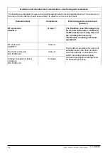

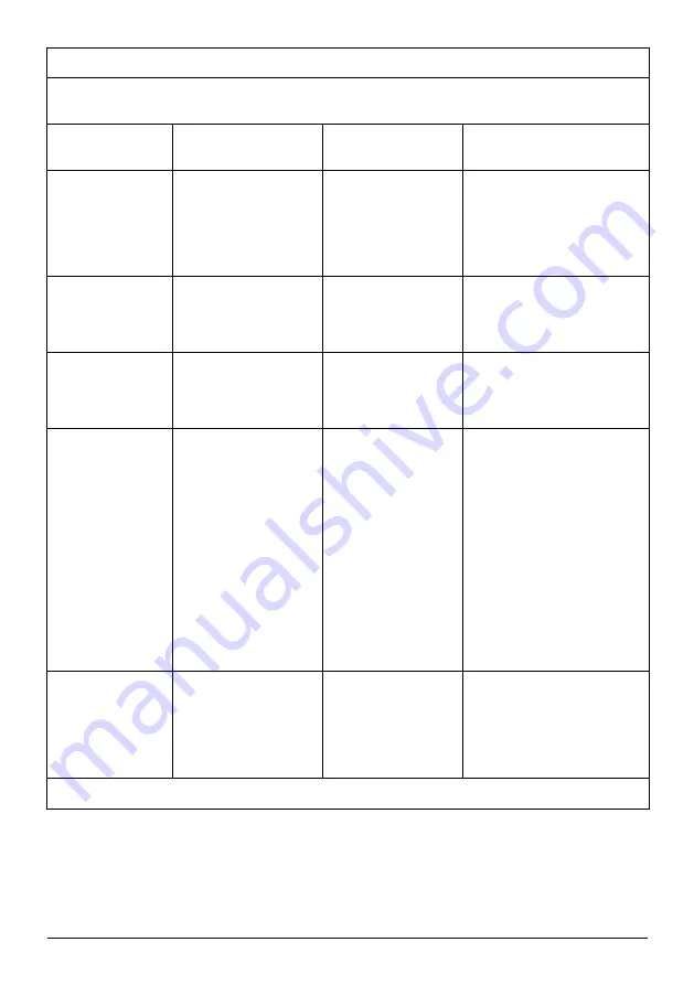
Guidance and manufacturer’s declaration – electromagnetic immunity
The EvaDrive is intended for use in the electromagnetic environment specified below. The customer
or the user of the EvaDrive should assure that it is used in such an environment.
Immunity test
IEC 60601 test level
Compliance level
Electromagnetic
environment - guidance
Electrostatic
discharge (ESD)
IEC 61000-4-2
+/- 6 kV contact
+/- 8 kV air
+/- 6 kV contact
+/- 8 kV air
Floors should be wood,
concrete or ceramic tile.
If floors are covered with
synthetic material,
the relative humidity should
be at least 30 %.
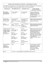
Electrical fast
transient / Burst
IEC 61000-4-4
+/- 2 kV for power
supply lines
+/- 1 kV for input/output
lines
+/- 2 kV for power
supply lines
+/- 1 kV
for input/
output lines
Mains power quality should be
that of a typical commercial or
hospital environment.
Surge
IEC 61000-4-5
+/- 1 kV differential
mode
+/- 2 kV common mode
+/- 1 kV differential
mode
+/- 2 kV
for
common mode
Mains power quality should be
that of a typical commercial or
hospital environment.
Voltage dips, short
interruptions and
voltage variations
on power supply
input lines
IEC 61000-4-11
<5 % U
T
(>95 % dip in U
T
)
for 0,5 cycle
40 % U
T
(60 % dip in U
T
)
for 5 cycles
70 % U
T
(30 % dip in U
T
)
for 25 cycles
<5 % U
T
(>95 % dip in U
T
))
for 5 sec
<5 % U
T
(>95 % dip in U
T
)
for 0,5 cycle
40 % U
T
(60 % dip in U
T
)
for 5 cycles
70 % U
T
(30 % dip in U
T
)
for 25 cycles
<5 % U
T
(>95 % dip in U
T
))
for 5 sec
Mains power quality should be
that of a typical commercial or
hospital environment. If the
user of the
[Equipment or
System] requires continued
operation during power mains
interruptions, it is recommended
that the [Equipment or System]
be powered from an
uninterruptible power supply or
battery.
Power frequency
(50/60 Hz)
magnetic field
IEC 61000-4-8
3 A/m
3
0
A/m
Power frequency magnetic
fields should be at levels
characteristic of a typical
location in a typical
commercial or hospital
environment
NOTE
U
T
is the a.c. mains voltage prior to application of the test level.
127
I N S T R U C T I O N S F O R U S E
System
RoMedic
TM


