
HandiQuilter.com
Page 13
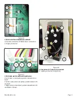
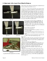
Figure 2.7
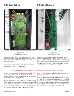
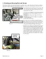
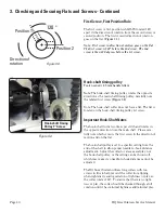
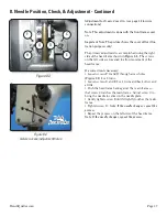
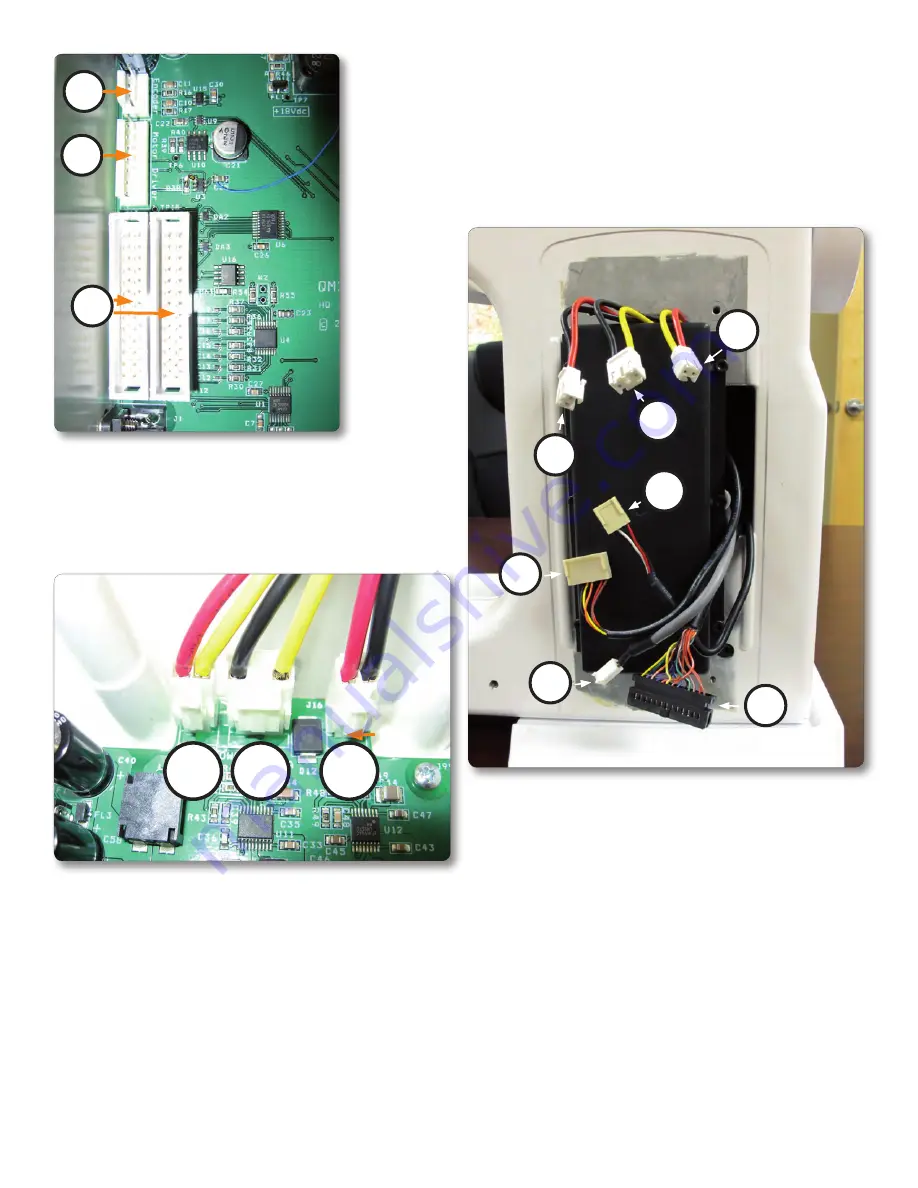
C-Pod Cable and Circuit Board Identifi cation
D: Left cable, red and yellow, position labeled J14 on
board.
E: Center cable, black and yellow, position labeled J15
on board.
F: Right cable, red and black, position labeled both J16
and Motor on board.
A
B
C
Figure 2.6
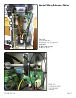
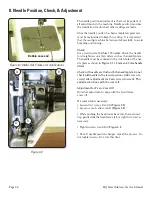
C-Pod Circuit Board Identifi cation (Detail)
A: Encoder connection. B: Motor driver connection.
C: Display Connector
D
E
F
Figure 2.8
C-Pod cables (A-F) shown disconnected
G: Lighting connection for light ring
J14
J15
J16
Motor
D
C
E
A
F
B
G


